162
Options List
C.15.5
Option 19 Firmware Setup
There is no setup in firmware for this option.
C.15.6
Connections
All connections to the rear-panel terminal strip should be made using spade lugs or ring lugs
suitable for use with #6 screws.
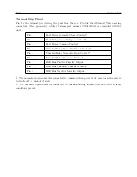
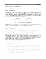
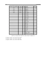
Refer to Figure C.17 and the specifications given above for
terminal assignments. The designations normally-open and normally-closed refer to the position of
the relay contacts during normal operation, prior to encountering an out-of-lock condition. This is
a fail-safe relay; it is in the faulted state with power OFF.
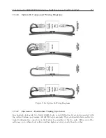
Figure C.18: Option 19 Relay Connections
Note that in the above diagrams, n.c. and n.o. correspond to the rear-panel terminal markings, and
refer to the condition when the relay is energized (normal clock operation).
C.15.7
Configuration
After the connections have been made, configuration of the fault relay is accomplished in the same
manner as configuration of the Out-of-Lock function (the relay is driven internally by the Out-of-
Lock circuitry). The Out-of-Lock function is enabled and configured using the SETUP menu for
the 1088B, which is described in Section 5 of the 1088B Operation Manual.
The SETUP menu allows entry of a value between 00 and 99 for Out-of-Lock Delay Time. The
delay time value represents the amount of time, in minutes, that satellite synchronization must be
continuously lost before the instrument outputs an Out-of-Lock signal and simultaneously activates
the Out-of-Lock relay. If the value is set to 00, the Out-of-Lock function is disabled, and the Out-
of-Lock output and the relay are both in the locked state whenever power is on.
The procedure for setting the Out-of-Lock function is as follows:
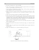
1. With the clock power turned on, press the SETUP key. The display should change to read,
SET RS-232?.
2. Press the SETUP key repeatedly, until the display reads, SET OUT-OF-LOCK?. Press the
ENTER key to select the Out-of-Lock sub-menu. The current out-of-lock delay time (between
00 and 99) will be displayed.
3. Pressing the UP and DOWN keys will change the selection. When the desired out-of-lock
delay time is displayed, press the ENTER key to confirm the choice and return to the first
level of the SETUP menu. To return the 1088B to normal operation, press one of the function
keys in the top row of the front panel keyboard.
Summary of Contents for 1088A
Page 4: ...iv ...
Page 6: ...vi ...
Page 18: ...xviii LIST OF FIGURES ...
Page 23: ...1 4 Attaching Rack Mount Ears to 1088A B Series Clocks 3 Figure 1 2 Attaching Rack Mount Ears ...
Page 24: ...4 Unpacking the Clock ...
Page 32: ...12 Front and Rear Panels ...
Page 38: ...18 Connecting Inlet Power Input and Output Signals ...
Page 46: ...26 GPS Antenna and Cable Information ...
Page 48: ...28 Setting Internal Jumpers Figure 5 1 Model 1088B Main Board ...
Page 76: ...56 The Setup Menus ...
Page 112: ...92 Serial Communication and Command Set ...
Page 127: ...B 4 Physical Dimensions 107 Figure B 1 Suggested Mounting of the AS0094500 Surge Arrester ...
Page 128: ...108 Using Surge Arresters ...
Page 145: ...C 5 Option 04 Parallel BCD Output 125 Figure C 4 Option 04 Output Jumper Settings ...
Page 146: ...126 Options List Figure C 5 Option 04 Board Layout and Jumper Locations ...
Page 166: ...146 Options List Figure C 12 Option 17 Board Layout and Jumper Locations ...
Page 187: ...C 16 Option 20A Four Fiber Optic Outputs 167 Figure C 22 Option 20A Jumper Locations ...
Page 194: ...174 Options List Figure C 24 Option 23 Internal Jumper Setup ...
Page 196: ...176 Options List Figure C 25 Option 27 Jumper Locations ...
Page 214: ...194 Options List Figure C 28 Option 29 Connector Signal Locations ...
Page 270: ...250 Options List ...


