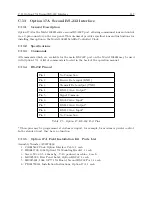
C.13 Option 17A Second RS-232 Interface
149
C.13.7
Installation
Physical Installation
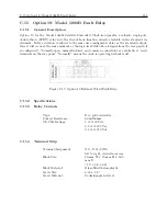
Option 17A may be installed in a Model 1088B Satellite-Controlled Clock by performing the fol-
lowing steps:
1. Disconnect the power source from the instrument.
2. Using a T-25 torx driver (or large slot screwdriver), remove the four screws holding the
instrument top cover in place. Remove the cover.
3. Locate the rear-panel opening for optional I/O connectors. When viewing the instrument
from the front, the opening is located at the right-rear, and is covered by a plate.
4. Using a T-10 torx driver, remove the two screws holding the cover plate, and remove the
cover plate. Save the screws.
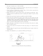
5. Insert the Option 17A Bracket (HD0043700) included with Option 17A kit in place of the old
cover plate, but do not install the screws.
6. Carefully punch two holes in the Mylar tape on the bottom of the option board to allow
screws to pass through the Option 17A board and the mounting bracket.
7. Position the Option 17A circuit board over the four mounting studs, with the 9-pin connector
protruding through the rear-panel opening.
8. Secure the option board and the cover plate in place, using the two screws removed in step 4
and the two screws included with Option 17A.
9. Install the interconnect cable between J9 on the Model 1088B main circuit board and J1
on the Option 17A circuit board. The connectors on the cable are keyed so as to prevent
backwards installation.
10. Install the middle connector if a second option board is already installed in option slot A
(located between Option 17A and the main board).
11. Replace the instrument top cover and screws, restore input power, and turn the instrument
ON.
Firmware Configuration
The internal operating firmware for the Model 1088B must be configured to recognize that the
Option 17A has been installed. This is accomplished by performing the following steps:
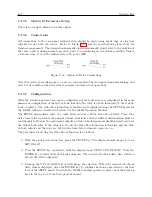
1. Enter the Setup Menu by pressing the SETUP key.
2. Press the UP key repeatedly, until the display reads SET OPTION BOARD. Press the EN-
TER key.
3. The display will indicate whether an option is installed in Option Slot A. Press the ENTER
key to confirm this status without changing it.
Summary of Contents for 1088A
Page 4: ...iv ...
Page 6: ...vi ...
Page 18: ...xviii LIST OF FIGURES ...
Page 23: ...1 4 Attaching Rack Mount Ears to 1088A B Series Clocks 3 Figure 1 2 Attaching Rack Mount Ears ...
Page 24: ...4 Unpacking the Clock ...
Page 32: ...12 Front and Rear Panels ...
Page 38: ...18 Connecting Inlet Power Input and Output Signals ...
Page 46: ...26 GPS Antenna and Cable Information ...
Page 48: ...28 Setting Internal Jumpers Figure 5 1 Model 1088B Main Board ...
Page 76: ...56 The Setup Menus ...
Page 112: ...92 Serial Communication and Command Set ...
Page 127: ...B 4 Physical Dimensions 107 Figure B 1 Suggested Mounting of the AS0094500 Surge Arrester ...
Page 128: ...108 Using Surge Arresters ...
Page 145: ...C 5 Option 04 Parallel BCD Output 125 Figure C 4 Option 04 Output Jumper Settings ...
Page 146: ...126 Options List Figure C 5 Option 04 Board Layout and Jumper Locations ...
Page 166: ...146 Options List Figure C 12 Option 17 Board Layout and Jumper Locations ...
Page 187: ...C 16 Option 20A Four Fiber Optic Outputs 167 Figure C 22 Option 20A Jumper Locations ...
Page 194: ...174 Options List Figure C 24 Option 23 Internal Jumper Setup ...
Page 196: ...176 Options List Figure C 25 Option 27 Jumper Locations ...
Page 214: ...194 Options List Figure C 28 Option 29 Connector Signal Locations ...
Page 270: ...250 Options List ...


