84
Serial Communication and Command Set
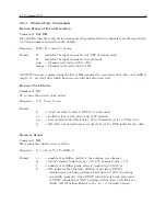
Return Latitude
Command:
LA
LA returns the current antenna latitude. In Position Hold mode, LA returns the current position-
hold latitude setting. In Fix mode, LA returns the most recent computed latitude value (calculated
each second).
Response:
Ndd:mm:ss.sss
C
Format:
N
= North (S for South)
dd
= degrees
mm
= minutes
ss.sss = seconds (fractional seconds)
Return Longitude
Command:
LO
LO returns the current antenna longitude. In Position Hold mode, LO returns the current position-
hold longitude setting. In Fix mode, LO returns the most recent computed longitude value (calcu-
lated each second).
Response:
Wddd:mm:ss.sss
C
Format:
W
= West (E for East)
ddd
= degrees
mm
= minutes
ss.sss = seconds (fractional seconds)
Position–Hold – OFF
Command:
PH0
PH0 deactivates the Position–Hold timing mode. The receiver resumes computing time and position
solutions approximately each second. This is referred to as the Fix mode.
Response:
C
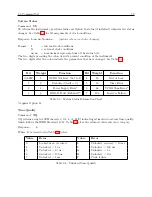
Position–Hold – ON
Command:
PH1
PH1 activates the Position–Hold timing mode. In this mode, the receiver position is held fixed
and each channel is used to compute a timing solution. These solutions are averaged together,
resulting in reduced timing noise due to to Selective Availability and RF channel noise. To operate
properly, the position used by the receiver must be fairly accurate. Due to the risk that previously
stored position data may be inaccurate, exercise caution when activating the Position–Hold mode
without either performing an Auto Survey or getting the position directly. Failure to observe these
precautions may result in serious timing errors.
Response:
C
Summary of Contents for 1088A
Page 4: ...iv ...
Page 6: ...vi ...
Page 18: ...xviii LIST OF FIGURES ...
Page 23: ...1 4 Attaching Rack Mount Ears to 1088A B Series Clocks 3 Figure 1 2 Attaching Rack Mount Ears ...
Page 24: ...4 Unpacking the Clock ...
Page 32: ...12 Front and Rear Panels ...
Page 38: ...18 Connecting Inlet Power Input and Output Signals ...
Page 46: ...26 GPS Antenna and Cable Information ...
Page 48: ...28 Setting Internal Jumpers Figure 5 1 Model 1088B Main Board ...
Page 76: ...56 The Setup Menus ...
Page 112: ...92 Serial Communication and Command Set ...
Page 127: ...B 4 Physical Dimensions 107 Figure B 1 Suggested Mounting of the AS0094500 Surge Arrester ...
Page 128: ...108 Using Surge Arresters ...
Page 145: ...C 5 Option 04 Parallel BCD Output 125 Figure C 4 Option 04 Output Jumper Settings ...
Page 146: ...126 Options List Figure C 5 Option 04 Board Layout and Jumper Locations ...
Page 166: ...146 Options List Figure C 12 Option 17 Board Layout and Jumper Locations ...
Page 187: ...C 16 Option 20A Four Fiber Optic Outputs 167 Figure C 22 Option 20A Jumper Locations ...
Page 194: ...174 Options List Figure C 24 Option 23 Internal Jumper Setup ...
Page 196: ...176 Options List Figure C 25 Option 27 Jumper Locations ...
Page 214: ...194 Options List Figure C 28 Option 29 Connector Signal Locations ...
Page 270: ...250 Options List ...

