background image


28 

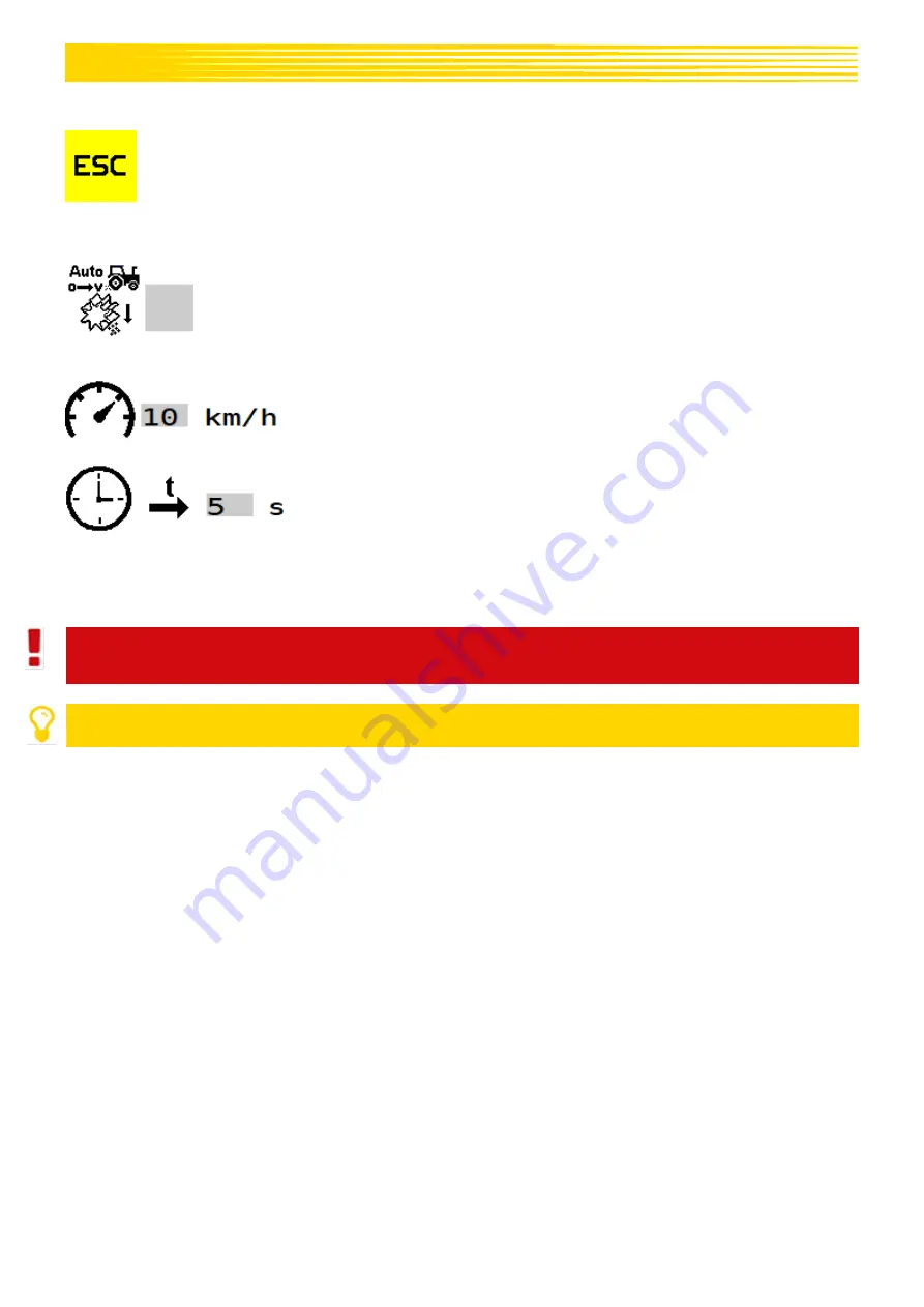
Description of the button functions 


With the ESC button, the entries are confirmed and you go back one menu level; in this 
case, to the Set menu. 


Description of the display elements 


Here, the automatic pre-metering can be activated.  
When  it  is  activated,  every  time  the  implement  is  lowered  at  the 
beginning  of  the  field  (during  the  transition  of  the  implement  into 
working position), pre-metering is started with the set speed for the 
set duration. 


Here,  the  speed  at  which  the  pre-metering  should  be  performed  is 
set. This speed is also used for manual pre-metering. 


Here, the time during which the automatic pre-metering should run is 
set. 

6.3.6


TASK CONTROLLER MENU 

The settings required for the Task Controller differ depending on the set Connector Type. 


CAUTION!  
It is mandatory to observed the tractor settings! 


PLEASE NOTE! 
If there is no valid calibration test, TC mode cannot be used. 


Summary of Contents for ISOBUS M2

Page 1: ...ISOBUS M2 OPERATING MANUAL PLEASE READ CAREFULLY BEFORE INITIAL OPERATION Translation of the original operating instructions Version 1 0 EN Item number 00602 3 530 ...

Page 2: ...2 Performing a calibration test 22 6 3 4 Tractor settings menu 25 6 3 4 1 Performing the calibration test 26 6 3 5 Pre metering menu 27 6 3 6 Task Controller menu 28 6 3 6 1 Task Controller menu for mounted implements 29 6 3 6 2 Task Controller menu for towed implements 30 6 3 7 Empty hopper 31 6 3 8 Fan menu 32 6 3 8 1 Electric fan electric fan Plus 32 6 3 8 2 Hydraulic fan 32 6 4 Info menu 34 6 ...

Page 3: ... 46 12 1 Extension cable 46 12 2 Splitter cable APV external 46 12 3 Splitter cable APV APV 47 12 4 Calibration button 47 12 5 Linkage sensor chassis 47 12 6 Linkage sensor top link 47 12 7 Linkage sensor pull switch 47 12 8 Sensor for linkage hydraulic system 48 12 9 Fill level sensor for PS 48 13 CONNECTION DIAGRAMS 48 13 1 PS 120 PS 500 48 13 2 PS 300 TWIN 50 13 3 PS 800 PS 1600 52 ...

Page 4: ...stions regarding spare parts To order maintenance and repair work Service address APV Technische Produkte GmbH ZENTRALE Dallein 15 A 3753 Hötzelsdorf AUSTRIA Telephone 43 2913 8001 5500 Fax 43 2913 8002 Email service apv at Web www apv at 3 WARRANTY Please check the controller device for any transport damage immediately upon receipt Later claims regarding transport damage can no longer be consider...

Page 5: ...CU to all of the actuators sensors and the connection cable to the ISOBUS socket on the tractor Figure 3 1 24 pin plug connection to controller ECU 2 12 pin plug connection to external sensors Speed sensors Working position sensors 3 2 pin plug supply to motor module 4 Open wire ends terminals on the seeder for Seeding shaft motor Motor module only for electric fan Filling level sensor Calibration...

Page 6: ...values could be lost 4 4 INSTALLATION MATERIAL AND OTHER ACCESSORIES Depending on the implement configuration the corresponding installation material covers and other parts will be supplied Details about the different versions can be found in the enclosed conversion instructions 5 INITIAL OPERATION 5 1 GENERAL INFORMATION ON THE CONTROLLER 5 1 1 STATUS BAR The status bar is located in the upper ar...

Page 7: ...ow the position or the utilised signal of the working position is changed 5 1 2 STOP BUTTON The STOP button can be found in every menu This button executes a general STOP of all motors Figure 6 Description of the button functions Grey no actuators are switched on Red motors are switched on and can be stopped with this button 5 2 BASIC SETTINGS MENU For initial operation or when pressing and holdin...

Page 8: ... is restarted By pressing and holding this button for 5 seconds a factory reset is performed i e all of the settings are reset and the Basic settings menu is called up again Description of the display elements Selection of the implement type The following selections are available PS120E PS120H PS200E PS200H PS300E PS300H PS300E TWIN PS300H TWIN PS500E PS500H PS800H PS1600H or LF600 Here E stands f...

Page 9: ... the PS TWIN implement type one seed type with part width section function two seed types across the same working width Selection of the existing PS fan The following selections are available electric fan electric fan PLUS hydraulic external fan or no fan OFF When using a hydraulic fan you must select whether a sensor is installed on the PS for fan monitoring speed sensor Setting whether a calibra...

Page 10: ...splayed The Work menu is described in more detail under Point 6 2 The implement settings are entered in the Set menu Here a calibration test is performed the seed is selected or the forward speed is calibrated The Set menu is described in more detail under Point 6 3 If the button is pressed and held for 5 seconds the Basic settings menu is called up Here basic settings can be entered e g motor typ...

Page 11: ... functions With the button the spread rate can be increased during operation in 5 increments up to a maximum of 95 With the button the spread rate can be reduced during operation in 5 increments down to a minimum of 85 With the ESC button you go back one menu level in this case to the Start menu With the Info button the Seed info menu for the currently selected seed is shown The Seed info menu is ...

Page 12: ...released the current forward speed is used again to regulate the seeding shaft This allows you to avoid gaps in the seeded area at the beginning of the field or when standing still on the field With the 100 button the spread rate can be set back to the value determined during the calibration test If the implement type PS TWIN is selected in the basic settings see Point 5 2 an extended Work menu is...

Page 13: ...ent forward speed The black mark shows the forward speed set during the calibration test If the forward speed becomes too high or too low so that the required speed for the seeding shaft can no longer be maintained the bar is coloured red and an alarm is issued see Point 7 for controller messages Display of the seeded area and the spread quantity for each seed type Display of the current fan speed...

Page 14: ...troller such as mounting the implement axle and seeding rail distances as well as switch on off times can be entered The Task Controller menu is described in more detail under Point 6 3 6 With the ESC button you go back one menu level in this case to the Start menu Empty hopper menu here the hopper s can be emptied The Empty hopper menu is described in more detail under Point 6 3 7 Seed library he...

Page 15: ... working width the utilised seeding shaft and the desired calibration time are set Afterwards the correct seeding shaft speed is determined The calibration test is always performed for the currently set seed type The Calibration menu is described in more detail under Point 6 3 3 Tractor settings menu here the source for the forward speed and the working position can be selected and calibrated More...

Page 16: ...e Spread rate Unit kg ha seeds m2 l ha 6 3 1 1 SEED MENU In this menu all set parameters that were saved at last use of the seed type are displayed Figure 12 Description of the button functions This button takes you to the Seed info menu There the seeded area hours spread quantity and area output is displayed The Seed info menu is described in more detail under Point 6 3 1 2 ...

Page 17: ... library is described in more detail under Point 6 3 1 With this button you go to the Calibration menu There the parameters can be changed and a new calibration test can be performed The Calibration menu is described in more detail under Point 6 3 3 Description of the display elements Display of the number and the seed name Display of the spread rate in kg ha or seeds m Display of the working widt...

Page 18: ...nter is reset to 0 Description of the display elements Display of the trip counter The trip counter can be reset by pressing and holding the Delete button for 2 seconds Display of the total counter The total counter can only be set to 0 by deleting the seed type 6 3 2 FILL MENU Here the current hopper fill level can be entered This forms the basis for the calculated possible remaining distance qua...

Page 19: ...ere the calculation of the remaining area distance can be switched on and off Here the current fill quantity of the hopper can be entered or displayed Here you can set the calculated still possible remaining area distance at which the fill level message should appear Here the output of the warning message for the fill level sensor can be activated or deactivated ...

Page 20: ...n test are entered Figure 15 Description of the button functions With this button you go back one menu level Either to the Set menu the seed library or the Seed menu depending on where you entered the Calibration menu from Here you can select whether the calibration test is performed in kg ha or seeds m By pressing and holding the Start button for 2 seconds the calibration test is started ...

Page 21: ...it must be ensured that the stored seeding shaft is used again otherwise the calibration test must be repeated Here the desired calibration time 0 5 min 1 min or 2 min or area 1 40 ha 1 20 ha 1 10 ha can be set When selecting an area the calibration time will be automatically calculated and displayed When using a calibration button available as an accessory this point is hidden CAUTION If values a...

Page 22: ...e the minimum and maximum calculated working speed will be shown 6 3 3 2 PERFORMING A CALIBRATION TEST During the calibration test the suitable seeding shaft speed is determined for the selected settings see Point 6 3 3 PLEASE NOTE A proper calibration test is important as it is the only way to ensure that your desired spread rate is achieved The calibration test must be performed as follows ...

Page 23: ... spread rate see Point 6 3 3 1 starts counting up 7 Calculation of the spread rate is automatically stopped as soon as the set calibration time has expired or when the calibration button is released 8 The calibrated seed is weighed and the determined weight is entered in the input box highlighted in grey on the calibration test results page see Point 6 3 3 1 CAUTION The weight of the calibration b...

Page 24: ... to the Work menu confirm with the OK button If you want to go to the seed library press the ESC button Figure 18 PLEASE NOTE Any changes to the saved calibration parameters requires repetition of the calibration test ...

Page 25: ...utton functions With the ESC button you go back one menu level In this case to the Set menu By pressing and holding this button for 2 seconds the 100 meter calibration test is started The following INFO appears Drive for 100 m then press 100 m STOP This button only appears when the speed source is set to external radar GPS or external wheel The 100 m Stop button appears as soon as the calibration ...

Page 26: ...lement Simulated the speed is adopted from the speed set in the calibration test Displays the current calibration value for the wheel radar or GPS sensor This symbol only appears when the speed source is set to external radar GPS or external wheel Shows whether an acoustic signal is activated or not when the working position is changed Shows the current working position source The following parame...

Page 27: ... axle over the mark 7 As soon as the tractor comes to a stop the 100 m Stop button is pressed and held for 2 seconds If the calibration was successful the message Calibration successful value accepted will be displayed The calibration value is now saved If the calibration was not successful the message Calibration invalid original value restored is shown and the original value is set see Point 7 f...

Page 28: ...n of the implement into working position pre metering is started with the set speed for the set duration Here the speed at which the pre metering should be performed is set This speed is also used for manual pre metering Here the time during which the automatic pre metering should run is set 6 3 6 TASK CONTROLLER MENU The settings required for the Task Controller differ depending on the set Connec...

Page 29: ... display elements Here the desired mode can be set There is a choice between ON OFF or AUTO Here the connection of the implement to the tractor can be set If the implement is mounted a selection can still be made as to whether it is mounted at the rear Rear or at the front Front Here the horizontal distance A from the reference point of the tractor to the seeding rail is entered The reference poin...

Page 30: ...t is described under Point 7 1 2 6 3 6 2 TASK CONTROLLER MENU FOR TOWED IMPLEMENTS Figure 26 Description of the button functions The functions correspond to the button functions for mounted implements see Point 6 3 6 1 Description of the display elements Here the horizontal distance A from the reference point of the tractor to the trailer axle and the horizontal distance B from the reference point...

Page 31: ...n the same screen With the ESC button the emptying is terminated and you automatically go back one menu level in this case to the Set menu If this button is pressed and held for 2 seconds the emptying procedure is started and the seeding shaft rotates at 100 If the implement type PS TWIN is selected in the basic settings see Point 5 2 an extended Empty hopper menu is available It is described unde...

Page 32: ...one menu level In this case to the Set menu Description of the display elements Here the desired speed for the electric fan can be set The fan speed must be selected according to the seeder operating manual 6 3 8 2 HYDRAULIC FAN In this menu various settings can be entered for the hydraulic fan The number of pulses from the speed sensor and the speed limits for the hydraulic fan can be set Figure ...

Page 33: ... 5 pulses per revolution More detailed information on this can be found in the operating manual conversion instructions for the respective seeder Display of the current fan speed Here the speed and the alarm limits for the hydraulic fan can be set If 0 revolutions per minute is entered for min the error message Fan speed too low will be deactivated NOTE the speed itself can only be adjusted throug...

Page 34: ...rt menu By pressing and holding the Delete button for 2 seconds the respective day counter is reset to 0 Description of the display elements The trip counters show the worked area the operating hours and the area output since the last reset The total counter shows the total worked area the total operating hours and the average area output of the control box TIP The trip counters can be used e g fo...

Page 35: ... the sensors the supply voltage and the power consumption of the motors Figure 31 Description of the button functions With the ESC button you go back one menu level in this case to the Start menu Description of the display elements Switching states of the individual sensors Linkage sensor input Fan speed sensor input Fill level sensor input ...

Page 36: ...th behind each other This is set in the Basic settings menu with the Number of seed types to be spread display element see Point 5 2 7 1 SPREADING OF TWO SEED TYPES If 2 is selected for the Number of seed types to be spread display element in the Basic settings menu two seed types can be configured in the Work menu It must be ensured that the same working width is entered for both seed types If th...

Page 37: ...pective seeding shaft can be reduced during operation in 5 increments down to a minimum of 85 With this button the respective seeding shaft can be switched on or off If an electric fan is installed it will start running automatically Only then does the respective seeding shaft start rotating If the respective seeding shaft is activated the triangle at the top left on the bottom lights up green it ...

Page 38: ...th 7 1 2 TASK CONTROLLER MENU The Task Controller menu is described under Point 6 3 6 For the PS TWIN implement type this menu was extended Under this point only the changed buttons and their functions are described 7 1 2 1 TASK CONTROLLER MENU FOR MOUNTED IMPLEMENTS Figure 33 Description of the display elements Here the horizontal distances AI and AII from the reference point of the tractor to th...

Page 39: ...ead or the lower link for a ball head hitch 7 2 SPREADING OF ONE SEED TYPE If 1 is selected for the Number of seed types to be spread display element in the Basic settings menu one seed type can be configured in the Work menu Both seeding shafts are shown which can be switched on and off separately Likewise both sections can be individually switched on and off via the Task Controller Information o...

Page 40: ... 7 For the PS TWIN implement type this menu was extended Under this point only the changed buttons and their functions are described CAUTION Before emptying the calibration lid must be removed and the calibration bag must be attached see PS TWIN operating manual Figure 35 ...

Page 41: ...minimum and maximum speed for the current settings is also shown Figure 36 9 CONTROLLER MESSAGES 9 1 SUPPRESSING ACKNOWLEDGING MESSAGES An acknowledgement button appears simultaneously with a message which can be used to suppress messages for a specific period of time By pressing the OK button messages are acknowledged deleted as soon as the error has been rectified By pressing the Snooze button t...

Page 42: ...eels to increase the speed Tractor speed too high The forward speed is too high and the seeding shaft can no longer readjust Reduce the forward speed Use larger coarser seed wheels Use more seed wheels on each outlet Reduce the spread rate Tractor speed too low The forward speed is too low and the seeding shaft can no longer readjust Increase the forward speed Use finer seed wheels Use fewer seed ...

Page 43: ...dlights Check the battery Check the cabling Check the plugs check the alternator Motor is overloaded seeding shaft I Motor is overloaded seeding shaft II A seed shaft is not able to rotate The motor has been strained too long at its limits Switch off the control box Remove any foreign objects or similar from the seeding shaft or the agitator Switch off the agitator with well flowing seed Remove 1 ...

Page 44: ...ions on the seeder especially the ENC encoder Contact Customer Service 9 5 ERROR TC ON MODE If the TC mode is switched on the following messages are issued as errors As a result all actuators will be switched off for these warnings Display Cause Solutions TC units inconsistent Boom I TC units inconsistent Boom II The units for the specified values from the Task Controller do not match the expected...

Page 45: ... the fill level sensor screw on the rear side Reposition the fill level sensor Deactivate the fill level sensor see Point 6 3 2 No speed signal Speed signal is not available on the ISOBUS Wrong speed signal was selected Check the settings for the speed sensor see Point 6 3 4 No linkage signal Linkage sensor was not detected There is no linkage signal issued on the ISOBUS Check the signal source If...

Page 46: ... Point 4 3 included with the delivery of an ISOBUS PS The extension cable is available in two lengths 2 m and 5 m Order number 00410 2 221 2 m 00410 2 220 5 m Figure 37 Symbolic image PLEASE NOTE If multiple extension cables are used together the electrical power of the fan can be reduced 12 2 SPLITTER CABLE APV EXTERNAL With this cable an APV implement and an external implement can be operated vi...

Page 47: ...test and emptying of the hopper can be performed directly on the implement Order number 00410 2 185 Figure 40 12 5 LINKAGE SENSOR CHASSIS Through this sensor the seeding shaft of the PS can start and stop rotating automatically when lifting and lowering the implement Connection 12 pin plug on the side of the PS under the cover Order number 00410 2 173 Figure 41 12 6 LINKAGE SENSOR TOP LINK Through...

Page 48: ... pressure in the hydraulic system The rotation of seeding shaft is then automatically started or stopped Order number 00410 2 176 Figure 44 12 9 FILL LEVEL SENSOR FOR PS The fill level sensor triggers an alarm on the ISOBUS terminal when there is not enough seed in the hopper Order number 04000 2 269 Figure 45 13 CONNECTION DIAGRAMS 13 1 PS 120 PS 500 Electric fan Figure 46 ...

Page 49: ...bration button Black 0 75 4 1 Implement cable Red 0 75 12 V sensor supply 4 2 1 Motor module Blue 0 5 4 2 2 Fan speed sensor Brown 0 34 4 3 Fill level sensor Brown 0 34 4 4 Encoder Red 0 34 5 1 Implement cable Black 0 75 Sensor ground 5 2 1 Motor module Grey 0 5 5 2 2 Fan speed sensor Blue 0 34 5 3 Fill level sensor Blue 0 34 5 4 Encoder Black 0 34 6 1 Implement cable Brown 0 75 Electric fan PWM 6...

Page 50: ...input 8 3 Calibration button Brown 0 75 9 1 Implement cable White yellow 0 75 Fill level sensor input 9 3 Fill level sensor I White 0 34 10 1 Implement cable White green 0 75 Spare 11 1 Implement cable Brown yellow 0 75 Seeding shaft speed input 11 2 Encoder Brown 0 34 12 1 Implement cable Brown green 0 75 Spare Stripping length 10 mm 13 2 PS 300 TWIN Electric fan Figure 48 ...

Page 51: ...le Black 2 5 Ground 3 2 Seeding shaft motor I Red 1 5 3 3 Calibration button Black 0 75 3 4 Seeding shaft motor II Black 1 5 4 1 Implement cable Red 0 75 12 V sensor supply 4 2 1 Motor module Blue 0 5 4 2 2 Fan speed sensor Brown 0 34 4 3 Fill level sensor I fill level sensor II Brown 0 34 4 4 Encoder I encoder II Red 0 34 5 1 Implement cable Black 0 75 Sensor ground 5 2 1 Motor module Grey 0 5 5 ...

Page 52: ...yellow 0 75 Calibration button input 8 3 Calibration button Brown 0 75 9 1 Implement cable White yellow 0 75 Fill level sensor I input 9 3 Fill level sensor I White 0 34 10 1 Implement cable White green 0 75 Fill level sensor II input 10 3 Fill level sensor II White 0 34 11 1 Implement cable Brown yellow 0 75 Seeding shaft speed I input 11 2 Encoder I Brown 0 34 12 1 Implement cable Brown green 0 ...

Page 53: ... cable Black 0 75 Sensor ground 4 2 Fan speed sensor Blue 0 34 4 3 Fill level sensor Blue 0 34 4 4 Encoder Black 0 34 5 1 Implement cable Grey yellow 0 75 Fan status input 5 2 Fan speed sensor Black 0 34 6 1 Implement cable Blue yellow 0 75 Calibration button input 6 3 Calibration button Brown 0 75 7 1 Implement cable White yellow 0 75 Fill level sensor input 7 3 Fill level sensor White 0 34 8 1 I...

Page 54: ...54 NOTES ...

Page 55: ...55 NOTES ...

Page 56: ...APV Technische Produkte GmbH Zentrale Dallein 15 AT 3753 Hötzelsdorf Tel 43 2913 8001 office apv at www apv at ...

Reviews: