background image

PRODUCT OVERVIEW 


PCM-1015/PCM-1215 POS Monitor


11


 1.4 Specification  


Model Name 

PCM-1015 

PCM-1215 

Hardware Specification  

Display  15” TFT LCD display panel 

Active Area  304 (H) x 228 (V) mm 

Pixel Pitch  0.297 x 0.297 mm 

Resolution  1024 x 768 

White Luminance  225 cd/m2  

Contrast Ratio  700 

Response Time  8 msec (Typ, on/off) 

View Angle 

R / L 

70 /70 (Typ) 

U /D 

70 /70 (Typ) 

 
External I/O Interface 

Serial Port   

1 x COM port (DB9) 

Audio Jack   

1 x Line-in (option) 

USB Port   

2 x USB 2.0 A Type (output) 
1 x USB 2.0 B Type (input) 

VGA Port  1 x VGA-in (DB15) 

Power Input  1 x 12V/2.5A DC Jack 

OSD Button  MENU, LEFT, RIGHT, SELECT 

Power Button  1 x power switch on the 

bottom of monitor 

1 x power switch on the 
right side of stand. 

 
Optional Peripheral 

Magnetic Stripe 

Reader  


ISO 7811 option 1/2/3 track 

 
Powering 

Power Supply  DC 12V/2.5A 

36W/12V power adapter 
AC Rating: AC100V~240V 
DC 12V/3A 


Summary of Contents for PCM-1015

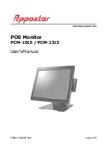
Page 1: ...POS Monitor PCM 1015 PCM 1215 User s Manual Edition JANUARY 2011 Version 1 00 http www appostar com...

Page 2: ...utlet on a circuit different from that to which the receiver is connected Consult the dealer or an experienced radio TV technician for help Declaration of Conformity These devices comply with part 15...

Page 3: ...make improvements to this publication from time to time in the contents hereof without obligation of the manufacturer to notify any person of such revision or changes Copyright This work is copyrighte...

Page 4: ...s dropped damaged or broken The product may cause a fire or electric shock when it is used improperly Observe the above safety measures at all times If the product is damaged immediately turn off the...

Page 5: ...I O INTERFACE AND OSD BUTTONS 10 1 4 SPECIFICATION 11 CHAPTER 2 HARDWARE INSTALLATION 13 2 1 PCM 1215 TOUCH MONITOR INSTALLATION 13 Connecting your Monitor 12 Magnetic Stripe Reader MSR Installation...

Page 6: ...PCM 1000 Series is available in 2 versions 15 Standalone Touch Monitor or built in second LCD for the POS terminal 1 1 Unpacking Confirm that all the following items are contained in the carton If an...

Page 7: ...PRODUCT OVERVIEW PCM 1015 PCM 1215 POS Monitor 7...

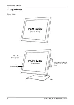
Page 8: ...PRODUCT OVERVIEW 8 PCM 1015 PCM 1215 POS Monitor 1 2 Appearance Front View 15 LCD Touch panel Front panel Base MSR module option Attachable on both sides PCM 1015 Second Display PCM 1215 Touch Monitor...

Page 9: ...PRODUCT OVERVIEW PCM 1015 PCM 1215 POS Monitor 9 Rear View Side View Tilt angle 0 90 degrees I O Cover Hinge cover Stand cover 90 Power button...

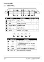
Page 10: ...n Audio Jack USB IN USB 2 0 Type B USB OUT x 2 USB 2 0 Type A COM Port DB9 F for Touch Function No OSD Button Description MENU Activate the On Screen Display OSD menu or scroll down the menu bar LEFT...

Page 11: ...R L 70 70 Typ U D 70 70 Typ External I O Interface Serial Port 1 x COM port DB9 Audio Jack 1 x Line in option USB Port 2 x USB 2 0 A Type output 1 x USB 2 0 B Type input VGA Port 1 x VGA in DB15 Powe...

Page 12: ...emperature 5 C 40 C Storage Temperature 20 C 60 C Operating Humidity 15 80 RH Storage Humidity 20 90 RH Mechanical Housing Color Cool White Dark Gray Construction ABS SECC Dimension W x D x H 355 x 32...

Page 13: ...e connectors on both the Host PC and monitor 3 Connect the DC 12V power cable to the 12V DC Jack 4 Connect the RS232 cable on both the Host PC and monitor to enable touch function 5 Connect the USB ca...

Page 14: ...Installation An optional MSR can be installed on both the right and left side of PCM 1215 By default the MSR is installed on the right side Step 1 Remove the cover from the MSR extension slot Step 2 C...

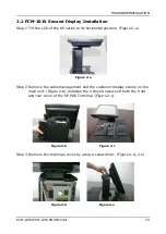
Page 15: ...zontal position Figure 2 a Figure 2 a Step 2 Remove the cable management and the customer display covers on the main unit Figure 2 b Unfasten the 2 thumb screws off both the front and rear cover of th...

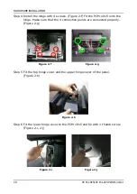
Page 16: ...015 onto the hinge Make sure that the 4 connection points are connected properly Figure 2 g Figure 2 f Figure 2 g Step 5 Fit the top hinge cover and the upper hinge cover of the panel Figure 2 h Figur...

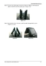
Page 17: ...Monitor 17 Step 5 Connect the VGA cable to both the VGA port DB15 and the power cable to both the 12V DC power jack Figure 2 k Figure 2 k Step 6 Reinstall the front the rear and the cable management...

Page 18: ...iver CD into your CD ROM drive Windows will automatically detect it and the Appostar Driver Installer appears on the screen If not locate the Setup exe file at CD and double click it to execute the in...

Page 19: ...ntinue f Select the Support Multi Monitor System option Click Next to continue g Select the Destination Folder or use the default one listed h Type a Folder name or use the default one listed Click Ne...

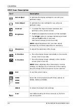
Page 20: ...the On Screen Display OSD menu or scroll down the menu bar LEFT Decrease setting value or scroll down the OSD main menu bar RIGHT Increase setting value or scroll up the OSD main menu bar AUTO Activat...

Page 21: ...OSD SETTING PCM 1015 PCM 1215 POS Monitor 21 OSD Language EXIT...

Page 22: ...ax 100 NOTE Adjust Brightness first and then adjust Contrast only if further adjustment is necessary Sharpness To adjust the sharpness of the image H Position V Position Move the display image horizon...

Page 23: ...g the Right and Left buttons min 0 max 100 OSD Timer The OSD stays active as long as it is in use Adjust the length of time the OSD remains active by changing the bar min 0 max 27 sec Signal Source Se...

Page 24: ...wer jack correctly 3 Check the BIOS setting 1 Enter the BIOS menu 2 Select the Advanced tab 3 Enter the Video Configuration 4 Confirm the Boot Display Device is preset to VGA LVDS 4 Check the Display...

Page 25: ...er is not working properly 1 Check whether the MSR is powered properly by the system if the buzzer beeps twice after restarting the system it means the MSR is powered correctly 2 Install the MSR drive...

Reviews: