6
803809 Rev. 01
6.
Locate the 24 Volt wiring harness either coiled
beneath the control box or shipped loose with the
unit. The harness is used to make connections to the
aquastat. It is also employed if a remote 24 Volt AC
wall thermostat will be used. Connect the multi-wire
24 volt wiring harness to the mating plug protruding
beneath the control box, as applicable, and follow the
detailed instructions on the wiring diagram affixed to
the specific unit being installed. Insulated crimp-on
connectors are provided at the end of every
connection lead to facilitate connections/insulation.
If
an aquastat will be not be used, you must connect
the ends (blue/orange) of the aquastat leads
together to permanently complete the aquastat
circuit.
7.
A 24 VAC water or steam valve output connector is
also provided under the control box. A mating
connector and 3 feet of wire leads are supplied to
connect to a 24 VAC valve. The units can
accommodate a normally-open NO or a normally-
closed NC valve. The NO/NC switch is located in the
high voltage wiring compartment as a DIP switch on
the electronic control board, and is factory set to NC.
The setting can be changed to NO in the field by
qualified service personnel.
WARNING:
The NO/NC conversion procedure
involves exposure to high voltage electrical circuits in
the control box in order to make the necessary change
to the DIP switch, and must be performed by qualified
service personnel. Failure to do so could result in
property damage, personal injury or death. Disconnect
electric power to the unit before servicing.
8.
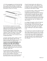
Locate the indoor air thermistor bulb at the end of the
black thermistor wire with clamp coiled beneath the
control box. The bulb and clamp must be relocated to
the thermistor holder in the bottom of the heating
subbase so it is sure to sense true return air
temperature, and not air that has been heated by the
heating coil. Use the clamp provided to secure the
bulb in place.
IMPORTANT:
To avoid damaging the indoor
thermistor wire, always remove the thermistor from the
clamp holder before removing the chassis for service.
IMPORTANT:
Operating the unit without the filter in
place can damage the unit, and void the warranty.
Always remember to re-install the filter after servicing
the chassis, or replacing/cleaning the filters.
9.
Wipe unit cabinet/wall sleeve to remove dirt, etc.
10.
The unit is now ready for operation, when supplied
with power from the distribution panel and wired to a
remote thermostat (if applicable).
START-UP CHECKLIST
Note: Once the unit is installed, it should be checked
for proper function by qualified service personnel
before turning it over to the User.
Circuit breakers, wire size, and electrical
connections tight and correct
Filter clean and properly in place
Condenser air inlet and outlet free of
obstructions and no short-circuiting of
condenser air
Unit operated for 20 minutes to prove stability
Controls operation OK
Unit installed in compliance with all codes and
ordinances
All panels in place and secured with required
fasteners
Mylar overlay applied to cover up touch pad
for 24 Volt Remote Thermostat installations.
Work area clean and free of debris
Owner or operator instructed on control
operation and routine maintenance.
USER CONTROLS - GENERAL
NFWC series is available with advanced-function
electronic controls with membrane switch type keypad.
ELECTRONIC CONTROLS
The chassis incorporating electronic controls is factory-
shipped with an active keypad control and display
mounted directly to the control panel. The unit
functions are controlled by the user by pressing the
keys on the keypad, and reading the display. However,
the unit also has the latent ability to be field-converted


