11
803809 Rev. 01
.125” thick non-adjustable louvers (
all provided in the
kit). To ensure proper operation it is important that
all installation instructions shipped with the duct
kit are strictly followed. What is presented in these
instructions is a basic overview only.
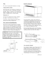
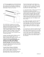
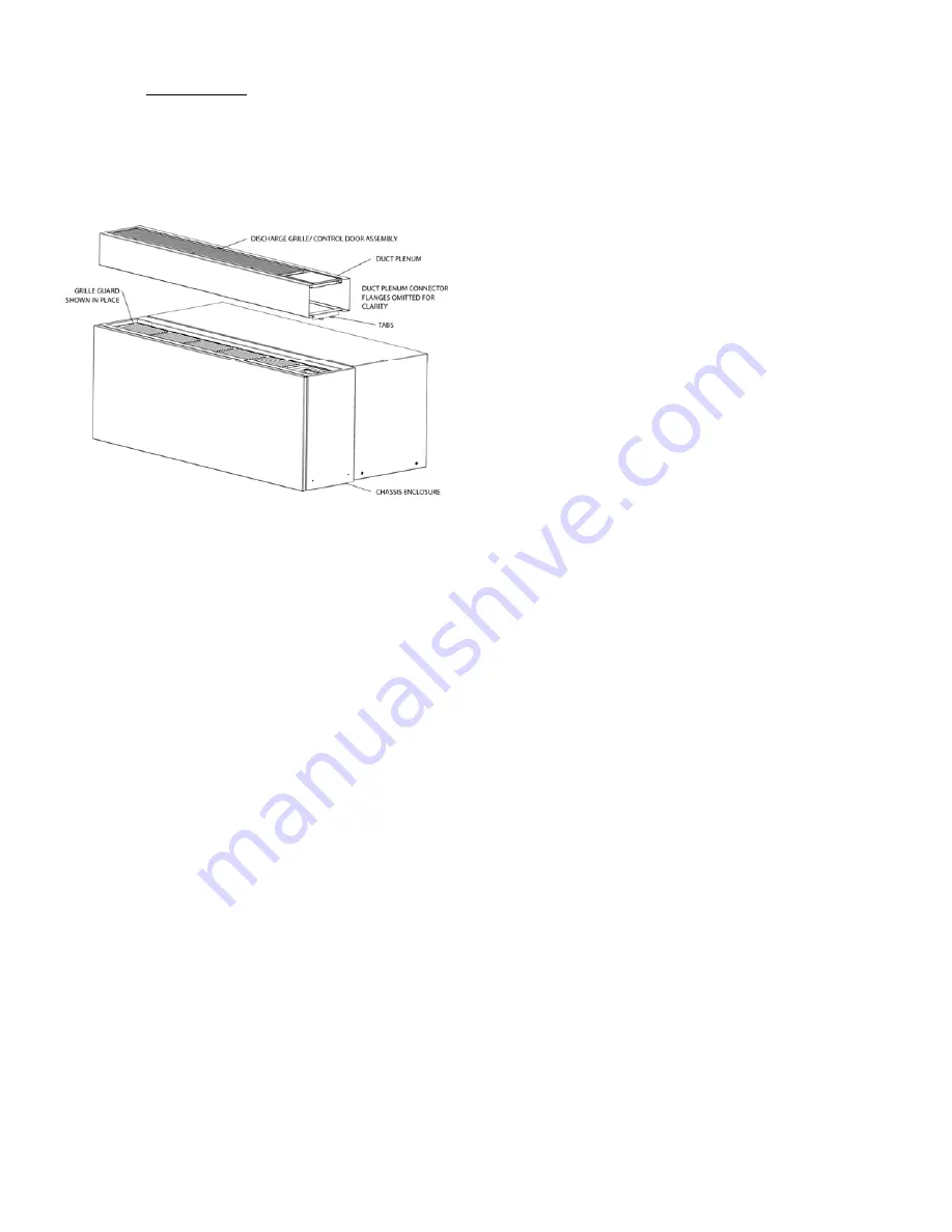
The Duct Plenum is designed to be reversible
(shown with right discharge) and is permanently
capped at one end. A decision is made whether to
duct right or left and the Duct Plenum is
positioned with the opening directed accordingly.
A strip of blank-off plates (not shown) is supplied
with the kit to allow the installer to snap off and
adjust the number of active plates required to
divert a given amount of air to the adjacent room
via the Extension Duct.
Using the maximum number of plates to restrict
the plenum outlet opening results in a 60%
physical blockage that will divert up to up to 50%
of the total air flow to the adjacent room.
To preserve the intended functionality of the
design, do not attempt to add additional
restriction to exceed the 60% maximum
amount of blockage.
The detailed installation
instructions shipped with the duct kit will provide
more detail regarding percent air diversion relative
to number of plates used.
To install the Duct Plenum, the Discharge
Grille/Control Door assembly must first be
removed from the Chassis Air Outlet by removing
the screw located under the control door.
The Duct Plenum can now be installed. Insert the
Duct Plenum tabs into the slots provided in the
Chassis Enclosure based on the direction you
require the air discharge. On the opposite end of
the tabs there will be an existing screw location.
Use the screw removed previously to secure the
Duct Plenum to the Chassis Air Outlet.
Lay the desired number of blank-off plates into the
Duct Plenum in accordance with the kit
installation instructions. Re-install The Discharge
Grille/Control Door assembly that was removed
from the Chassis Air Outlet so that the control
door is above the touchpad controls, and secure
using the screw provided in the kit. The Discharge
Grille/Control Door assembly should now reside
in the Duct Plenum outlet if the installation was
done correctly.
To complete the assembly, cut the 48” Extension
Duct to the desired length, slide it on to the
protruding flanges of the Duct Plenum outlet and
secure with the two beige screws provided, and
then terminate the duct with the Air Terminal
Grille by fastening it to the wall in the adjacent
room.
To give full access to remove the Chassis at a later
date, the Discharge Grille/Control Door assembly
can be removed with a single screw to give access
to the Duct Plenum, and the Duct Plenum can be
removed with a single screw by pulling slightly
upward and sideways on the capped end, once the
two beige screws have been removed from the
duct extension.


