CSP-CSPS-8000/B Section 1 Page 15 of 30
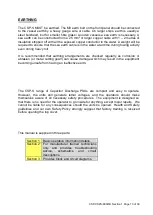
EARTHING - FURTHER REMINDER
THIS UNIT MUST BE EARTHED / GROUNDED BEFORE ANY POWER IS APPLIED.
FAILURE TO DO SO MAY REPRESENT A SEVERE HAZARD TO BOTH EQUIPMENT
AND PERSONNEL.
The front of the CSP-S must
be grounded to the ship’s ground
system. This is achieved by attaching a short length of thick wire or earth braid from the
CSP-S front panel earth stud, to an appropriate earthing point on the vessel. If a suitable
earth cannot be found, the CSP-S earth stud should be connected directly to the water
using an adequate length of heavy wire, with the insulation removed from the submerged
end in the water. A weight will also be necessary to keep the wire submerged when the
vessel is underway.
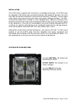
SYSTEM INTER-CONNECTIONS
OUTPUT CABLE CONNECTION
ENSURE POWER TO UNIT IS TURNED OFF BEFORE ANY CONNECTIONS ARE
MADE.
Connect the high voltage cable to the CSP-S front panel using the high voltage
connector. The HV connector has 2 small sensing pins which will deactivate the high
voltage if mains power is applied without the connector in place. Ensure the HV
connector is fully mated to the unit. The two larger sockets should never be at a high
potential but it makes sense never to attempt to touch these.
If you have our HV junction box, the two conductors of the acoustic source - boomer
plate or sparker should be connected to this before connecting to the CSP-S. The
terminal wing nuts should be tightened onto clean copper or tinned copper terminals. A
good connection is necessary as high currents pass through these terminals. Ensure that
the +ve or red terminal is connected to the + mark inside the HV Junction box. The black
or
–ve terminal should be connected to the – mark inside the HV junction Box. Ensure
that
the microswitch ‘clicks’ when the top cover is secured. The HV Junction Box can be
bulkhead mounted before the cover is secured. In the situation of the power cable /
sound source being caught on an object, the HV cable is pulled from the HV Junction
Box, rather than the CSP-S unit being pulled onto the floor.
The junction box is usually supplied with a 1.5 metre lead, terminated in our HV
connector. The junction box is fitted with a microswitch which is connected to sense pins
in the HV plug, ie deactivating the high voltage charger if the lid is removed and the
‘INTERLOCK’ light will illuminate.
Summary of Contents for CSP-S 4000
Page 2: ...CSP CSPS 8000 B Section 1 Page 2 of 30 ...
Page 3: ...CSP CSPS 8000 B Section 1 Page 3 of 30 OPERATION MANUAL Section 1 ...
Page 4: ...CSP CSPS 8000 B Section 1 Page 4 of 30 ...
Page 6: ...CSP CSPS 8000 B Section 1 Page 6 of 30 ...
Page 8: ...CSP CSPS 8000 B Section 1 Page 8 of 30 ...


