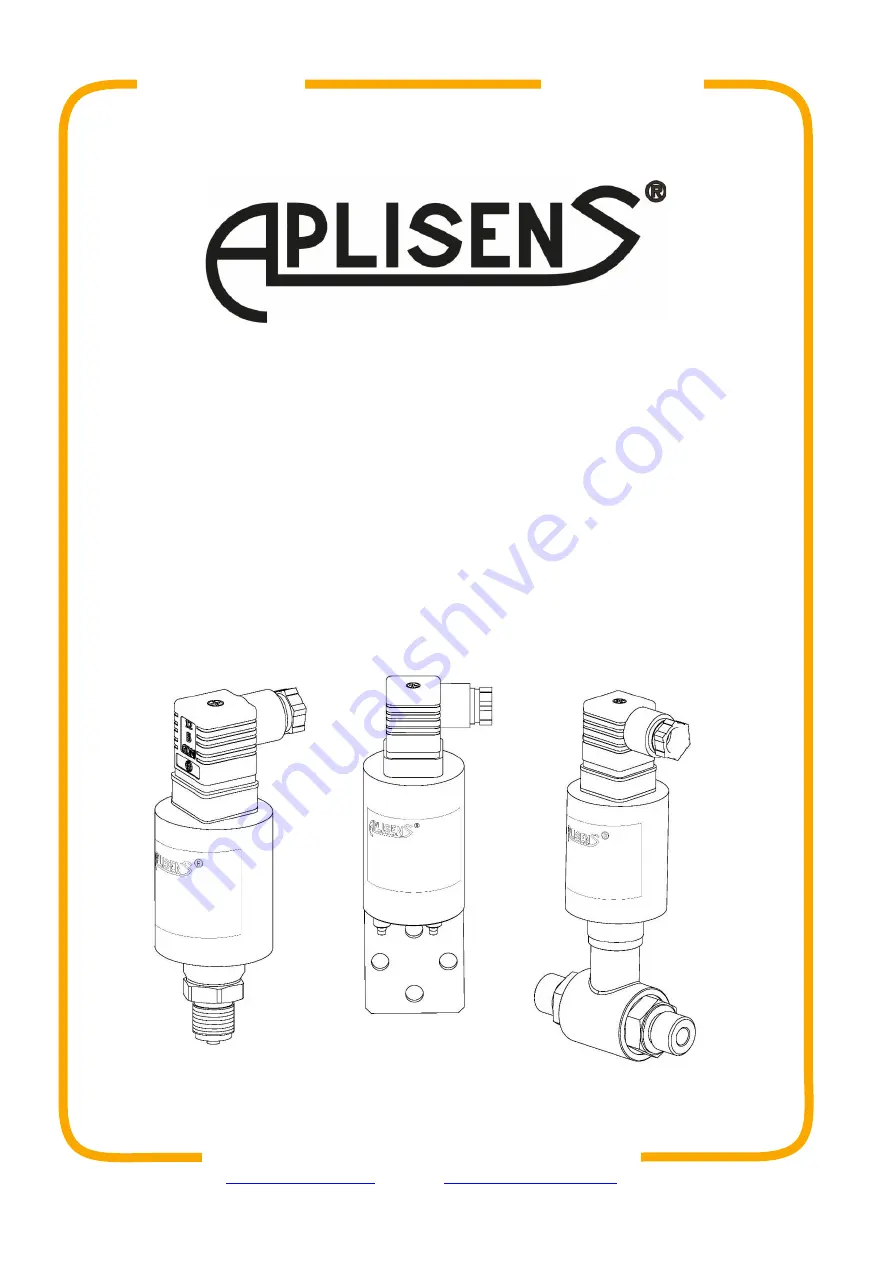
Aplisens PC-50 User Manual Download Page 1


USER’S MANUAL 


PRESSURE TRANSMITTERS 

PC-50 


DIFFERENTIAL PRESSURE TRANSMITTERS 

PR-50, PR-54, PRE-50G 


EN.IO.PC.PR.50 

MARCH 2022 

APLISENS S.A., 03-192 Warsaw, Morelowa 7 St. 

tel. +48 22 814 07 77; fax +48 22 814 07 78 

www.aplisens.com

e-mail

[email protected]


Revision 01.A.001 

Summary of Contents for PC-50

Page 1: ...ERS PC 50 DIFFERENTIAL PRESSURE TRANSMITTERS PR 50 PR 54 PRE 50G EN IO PC PR 50 MARCH 2022 APLISENS S A 03 192 Warsaw Morelowa 7 St tel 48 22 814 07 77 fax 48 22 814 07 78 www aplisens com e mail export aplisens com Revision 01 A 001 ...

Page 2: ...ies of certificates PC 50 ID 0049 0001 0000 0000 0000 0000 0001 87 https www aplisens pl ID 004900010000000000000000000187 PR 50 ID 0052 0001 0000 0000 0000 0000 0001 78 https www aplisens pl ID 005200010000000000000000000178 PRE 50G ID 0051 0001 0000 0000 0000 0000 0001 81 https www aplisens pl ID 005100010000000000000000000181 PR 54 ID 0053 0001 0000 0000 0000 0000 0001 75 https www aplisens pl ...

Page 3: ...al as well as with the electromagnetic com patibility and safety regulations and standards applicable to the type of installation In systems with I C equipment in case of leakage there is a danger to staff due to the medium under pressure All safety and protection requirements must be ob served during installation operation and inspections If a malfunction occurs the device should be disconnected ...

Page 4: ...ling specification 9 7 1 3 Grounding 10 7 1 4 Overvoltage protection 10 7 1 5 Shielding equipotential bonding 10 7 2 Transmitter power supply 11 7 2 1 Transmitter supply voltage 11 7 2 2 Resistance load in power supply line 11 7 3 Final inspection of cabling 11 8 START UP 12 8 1 Correction of impact of transmitter mounting position after installation 12 9 MAINTENANCE 13 9 1 Periodic inspections 13...

Page 5: ...s to install electrical and measuring devices the device shall be used according to its intended purpose in line with the permissible parameters specified on the nameplate Transmitter identification the protection elements used by the manufacturer to ensure transmitter safety may be less effective if the device is operated in a manner not consistent with its intended purpose before installing or d...

Page 6: ... shall be protected against movement and direct impact of atmospheric factors 3 3 Storage Transmitters shall be stored in a factory packaging in a room without vapours and aggressive sub stances protected against mechanical impact Allowable ambient and operating temperature range PC 50 40 80 C 40 176 F PR 50 PR 54 PRE 50G 25 80 C 13 176 F 4 GUARANTEE General terms and conditions of guarantee are a...

Page 7: ...ess connector Transmitter model ID Transmitter serial number Measuring range Supply voltage values Output signal Permissible range of ambient temperature Maximum static pressure IP protection rating Year of production Note about the obligation to read the manual Lower part of the nameplate Special executions 5 3 CE mark declaration of conformity The device has been designed to meet the highest saf...

Page 8: ... the separator diaphragm can only be removed shortly before installation Hydrostatic pressure of the manometric liquid column in the transmitter separator system may cause incorrect indication of the measured value After installation the transmitter must be pressure reset Do not clean or touch separator diaphragms using hard or pointy objects Separators with pressure transmitter form a closed cali...

Page 9: ...lock from the cover undermining it with the end of the screwdriver inserted into the slot provided for this purpose Connect the wires to the cube as shown in the picture below Figure 1 Electrical connection of the transmitter If the sealing of the cables in the gland is ineffective e g when single cables are con nected the opening of the gland must be sealed with a flexible sealing compound to ach...

Page 10: ...smitter is earthed through the pipeline and a possible cable screen is connected to the transmitter s power supply and measurement installation the func tional earthing terminal should not be used 7 1 4 Overvoltage protection Type of transmitter and electrical connection Protection between wires TVS di odes nominal voltages Protection between wires and earth and or enclosures type of protection no...

Page 11: ...trans mitters under normal operation conditions is defined as 0 02 A The maximum resistance value in the power circuit along with the power cables resistance is defined by the formula for 4 20 mA output for voltage output where USPLY voltage at the supply terminals of the 4 20 mA current loop V UMIN minimum supply voltage of transmitter Table 2 Permissible transmitter supply voltages RL_MAX maximu...

Page 12: ...and a milliammeter or a millivoltmeter for a relative pressure gauge transmitter with zero set for atmos pheric pressure The adjustment can be made after the transducer has been supplied with electricity the electrical connection has been partially disassembled and the appropriate potentiometer labelled zero is accessible At atmospheric pressure in the system the potentiometer should be used to re...

Page 13: ...harac teristics If there is no signal in the transmission line or its value is improper check the supply line connection status on terminal blocks connectors etc Check if the supply voltage and load resistance are correct 9 3 Cleaning washing To remove impurities from the external surfaces of the transmitter wipe it with a cloth dampened in water 9 3 1 Diaphragm cleaning The only possible method o...

Page 14: ...aste electrical and electronic equipment or returned to the manufacturer 11 HISTORY OF REVISIONS Revision No Document revision Description of changes DTR PRE 50G ENG 07 2012 1 DTR PRE 50G ENG Revision A 03 2014 Editorial changes 2 DTR PR 54 ENG 03 2016 3 01 A 001 2022 03 New document edition Change of electron ics update of supply voltage Developed by DBFD ...

Page 15: ......

Reviews: