


Read Instructions Thoroughly Before Use
SPECIFICATIONS
- 1500 Watts,120 Volts
CAUTION
(1 ) Have a qualified electrician install a properly grounded receptacle
outlet, acceptable for outdoor use and protected from snow and rain,
immediately adjacent to the location where the heater will be used, (2)
route the supply cord and locate the heater so as to be protected from
damage by livestock, (3) do not use extension cords, (4) inspect cord
before using, (5) unplug heater at receptacle outlet when not in use or
before removing from tank, (6) store heater indoors after winter season,
(7) heating element MUST be completely submerged while in use to
prevent risk of fire hazard, (8) do not tether unit and (9) Caution: to ensure
continued protection against electric shock hazard, connect to properly
grounded outlets only.
MAINTENANCE
Do not allow lime or other impurities in the water to build up on the
heating element. The frequency of cleaning depends directly upon the
composition of your water supply. To remove buildup, soak the heating
element in vinegar or a lime removing cleaner obtained at any farm or
hardware store. Then use a rough brush to scrub the element. Do not
use steel wool or something that will scratch the element. Inspect the
element for any cracks before reinstalling.
GROUND FAULT INTERRUPTER
Must be installed in the circuit. This is a very sensitive device that cuts off
the electrical current if there is any leakage of electricity in your water
tank. This device may be obtained from any electrician or hardware store.
WARRANTY
This de-icer is warranted 12 months from the date of purchase. If you
believe your de-icer is defective and still within the warranty period,
return it to the factory for inspection and possible replacement. The
warranty is voided if (1) the ground terminal on plug has been removed,
(2) excessive deposits have been allowed to accumulate on the heating
element, (3) there is evidence of general abuse such as animals chewing
on the cord. This warranty does not cover incidental or consequential
damage resulting from either a defect in parts, materials, or operation
failure. Some states do not allow the exclusion or limitation of the
above damages so the above limitation may not apply to you. No agent,
employee, or representative of Miller Manufacturing has any authority to
bind Miller Manufacturing to any affirmation, representation or warranty
directed towards any products bearing the Miller Manufacturing name,
except as stated herein. This warranty gives you specific legal rights. You
may also have other rights which vary from state to state.
INSTALLATION INSTRUCTIONS
1. Unscrew and remove the drain plug from the drainhole of your stock
tank. Save this plug because you will need to reinsert the drain plug
once the heating season is over and you have removed your de-icer
from the tank.
2. Remove the plastic nut from the de-icer.
3.
For use in a Rubbermaid tank:
We recommend that you remove the entire drain assembly. To remove
this assembly you must first remove the plastic nut found on the
outside of your Rubbermaid tank. This nut holds the drain assembly in
place. After the nut is removed, the drain assembly can be removed.
You should remove the threaded drain assembly, plastic nut and rubber
gasket. Save these items to be reinstalled in your tank after the heating
season. If you’re using a Rubbermaid tank and have removed the drain
assembly as described above, you should choose side “B” of the nut
as shown in figure 1. You will install your de-icer with this side facing
the tank.
For all other tanks:
You will note that the nut has two sides. One side is marked side “A”
and the other is marked side ”B”. You must determine which side of the
nut to place against the drain hole.
1. Determine the correct side by placing the nut against the drain hole on
the outside of the tank.Try to fit the diameter of the raised inner ring
of each side of the nut into the inner diameter of the drain hole (see
figure 1). Choose the side that fits most snugly. This will help secure
and center the de-icer within the opening of larger drain holes found
on some tanks.
2. If the raised inner ring (on both sides of the nut) shown in figure 1 is
larger in diameter than the drain hole diameter found on your tank,
then you may use either side of this nut. This indicates that the drain
hole is small enough to allow your de-icer to remain centered within
the drain opening.
3. If the nut is “bumping” into the ground or any other surface which the
tank rests on, you must shim under the tank to raise this area. The nut
should then twist freely.
4. Be sure to leave the rubber gasket on the threaded side of the de-icer
and against the plastic plate of the heater housing.
5. Set the de-icer on the inside of the tank. Let it rest on the bottom of
the tank. The rubber gasket should be between the inside of the tank
surface and the plastic plate of the heater housing (see figure 2).
6. Insert the power cord plug through the drain hole from the inside of
the tank. When using the 99DP, depending on the diameter of the tank
drain hole, you may have to separate the cord (see figure 3) and then
reassemble it after it has passed through the drain hole. Be sure to
align the arrows located on the outer diameter of the male and female
plugs before reassembly.
7. For installation through a wide range of drain holes, the power cord of
the 99DP can be disconnected as shown in figure 3. Note that there
is a rubber sleeve which protects this connection from moisture. This
sleeve should fit tightly over this connection.
This connection is
water resistant, NOT water-proof.
This connection should never be
placed directly in water as electrical shock will occur! This could result
in death or injury.
8. Test to be sure that the plastic plate and rubber gasket both fit flush
against the diameter of the drain hole from the inside of the tank.
a) If the bottom of the
plastic plate is bumping
into the bottom of
the tank surface and
preventing the de-icer
from laying flush against
the drain hole-snap the
plastic strip off along
the groove as shown
in figure 4. If breaking
this strip was necessary
then you must also
take a knife and cut the
overlapping piece of gasket.
9. Insert the plastic nut onto the cord using the “slot” in the nut. The
plastic nut should be inserted so the side chosen in step #1 is facing
toward the tank surface. If you have not completed step #1, you must
do so before attempting this step.
10. Tighten the nut onto the threaded stem of the heater housing and up
against the outside tank surface. Position the nut so that the raised
ring fully inserts into the drain hole of the tank (see figure 2 and 5).
This is only necessary if you have determined that this ring is of smaller
diameter than the drain opening in your tank as tested by completing
step #2. This will stabilize the de-icer.
11. Tighten this nut ‘’snug” but do not over tighten. Be sure the unit is
unable to twist in the tank.
If you are experiencing leaks:
a) Check to be sure the unit is fitting flush against the diameter of the
drain plug on the inside of the tank. See step #8.
b) Did you choose the correct size of nut? See step #1.
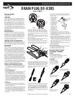
DRAIN PLUG DE-ICERS
Item # 99DP
304053
1
1
/
2
”
2”
FIGURE 1
Raised
inner
ring
Raised
inner
ring
FIGURE 2
Plastic
plate
Rubber
gasket
Tank
surface
Plastic
nut
FIGURE 4
UP
FIGURE 3
Miller Manufacturing, Glencoe, MN 55336 USA • www.miller-mfg.com
INSTRUCTIONS FOR THE
LOCKNDRY® CORDSET
FEATURES
- Plugs into any normal 3-prong outlet
- Mates with LOCKNDRY® plugs to form a water-resistant seal
- Keeps connection from separating during use
- Second, locking nut for secure connections
INSTRUCTIONS
(1) Insert the plug into the
receptacle just as you would a
normal extension cord making
sure the plug is fully inserted.
(2) Slide the large nut forward to
engage the threads on the plug.
(3) Rotate the nut to tighten the
plug against the receptacle.
(4) Slide the second, thinner, red nut
forward to engage the threads.
(5) Rotate the red nut snugly
against the larger nut.


