APEX PE Series
Paragraphic Equalisers
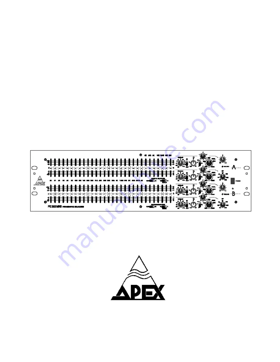
PE 232 MKII
USER MANUAL
APEX nvSchoebroekstraat, 623583 Beringen - BelgiumTel: +32 89 28 61 91
Page 1: ...APEX PE Series Paragraphic Equalisers PE 232 MKII USER MANUAL APEX nv Schoebroekstraat 62 3583 Beringen Belgium Tel 32 89 28 61 91...
Page 2: ......
Page 3: ...ains fuse 12 5 5 The rear pannel 13 5 6 Rack mounting 14 Section 5 Signal connections 15 5 1 Input 15 5 2 Output 16 5 3 Grounding 17 Section 6 The Equaliser 19 Section 7 General operating instructions...
Page 4: ...4...
Page 5: ...frequency Perfectly flat amplitude and phase response is obtained by using our DLT thick film hybrid circuits which surpasses the results and quality of discrete components DLT stands for Dynamic Lase...
Page 6: ...al filters of the graphic equaliser combine smoothly together and result in a continuous response curve free from The strength of the parametric filters is the possibility to control Q frequency and b...
Page 7: ...impedance to ground for each leg Both the input and output circuits are factory adjusted for optimum balance at low and high frequencies This results in increased interference immunity of the unit The...
Page 8: ...8...
Page 9: ...of gain available Extremely low distortion and noise True differential input circuitry Effective HF interference cancelation on in and outputs through perfectly HF balanced stages XLR in and outputs...
Page 10: ...10...
Page 11: ...plug proceed as follows The equaliser comes in a cardboard safety box specially designed for protection of the unit against damage during transport Save all the packing materials for future use if you...
Page 12: ...y turning the locking screw a half revolution counter clockwise and pull out the fuse holder of the socket Remove the old fuse and replace with fuse of the correct rating T630 mA slow blow fuse Little...
Page 13: ...ounding type attachment plug rated 15 A 125 V For units set at 230 V domestic USA use a UL listed cord set consisting of a minimum 18 AWG type SVT or SJT three conductor cord a maximum of 15 feet in l...
Page 14: ...nit while ensuring perfect mechanical stability Make sure there is enough room for air circulation between different pieces of equipment and through the heatsink at the back 14 4 SERIAL NUMBER This nu...
Page 15: ...ource HF and LF trims are provided to optimise the CMR and null out circuit tolerances These electronically balanced inputs are compatible with most professional and semi professional balanced or unba...
Page 16: ...of signal Output Some general rules for input connections Although not necessary because of input circuit symmetry it is best to always use the and input terminals when wiring the equaliser In this wa...
Page 17: ...ose who do not wish to completely disconnect the chassis and circuit grounds Providing a small ceramic capacitor between the two grounds can be helpful for solving HF buzz problems often encountered w...
Page 18: ...18 Figure A Figure B Figure C Figure D...
Page 19: ...hing circuit for better visualisation of overload conditions and will light for The LEVEL control adjusts the input level to the equaliser and filter sections of the unit Being preceded by the input s...
Page 20: ...of the Q The frequency control adjusts the centre frequency of the filter In combination with the multiplier switch the centre frequency can be positioned anywhere in the audible spectrum Calibration...
Page 21: ...equaliser section to 6dB or 12dB full scale Note The rotary controls of the PM232MKII are high quality conductive plastic potentiometers However calibration accuracy of these controls is only modest...
Page 22: ...22...
Page 23: ...panel illustrate the different functions of the unit and make it ergonomically pleasant to work General operating instructions The level control is preceding the filter section of the equaliser and l...
Page 24: ...sound while providing serious protection against overload HP filter If you have never used a parametric equaliser before the best thing to do is to experiment with actual program material It is hardl...
Page 25: ...ion you will find out that narrowband dips are essentially inaudible You can experiment with this using the IN OUT switch for comparing processed and unprocessed sound Infinite notches are very useful...
Page 26: ...ower and the sound will be more natural in this way Do not attempt to correct narrow peaks or dips with the graphic section Use the parametric filters for this purpose These aredesigned for narrowband...
Page 27: ...be reduced higher Q setting to minimize the loss of audio information Increase the gain of the system until it feeds back at a single frequency This is the major ring mode Make sure that from the mome...
Page 28: ...requencies are attenuated for decreasing the effect of windhowl in the microphone using the high pass filter with a 30 Hz cutoff Hum is easily suppressed with a parametric filter in the notch mode For...
Page 29: ...into 600 Impedance 51 eachleg Output symmetry balance better than 65dB 20Hz 20KHz IEC XLR 3 type connector connections 1 signal ground 2 hot 3 cold PERFORMANCE Frequency response 0 0 5dB 20Hz 20KHz g...
Page 30: ...Range of Q adjustment 0 5 to 8 Range of level adjustment to 15dB typ 45 to 15 5 dB non reciprocal Smaller cut than boost curves through addition and subtraction of parametric bandpass filter output to...
Page 31: ...ce tracks The rear panel can be cleaned in the same way as the front panel The top cover minimizes accumulation of dust inside the unit and should normally be in place when using the equaliser Dirt on...
Page 32: ...ve unit Name Company Adress Telephone Country Model No Serial No Purchased from Date Describe symptoms of malfunction Under what conditions does the malfunction occur A All the time B After a while C...
Page 33: ...resulting from Apex product failure This warranty shall be considered void if this product is subjected to repair work or alteration by persons other than authorised by Apex in such a manner as to in...
Page 34: ...responding changes in products previously manufactured from us Corrective action will be taken within a reasonable time of the date of receipt of the defective product by us or the service centre If t...