OPERATING MANUAL
FOR PRESSURE CONTROLLERS
Models PC · PCS · PC3 · IVC
Page 1: ...OPERATING MANUAL FOR PRESSURE CONTROLLERS Models PC PCS PC3 IVC ...
Page 2: ...ute gauge and differential pressure controllers Remote sensing pressure controllers Integrated vacuum controllers external sensor pressure controllers For support or questions regarding the use or operation of this device please contact support using the information on page 16 Serial Next Calibration This device comes with a NIST traceable calibration certificate This device conforms to the Europe...
Page 3: ...2021 08 19 REV 0 PRESSURE CONTROLLER OPERATING MANUAL 3 ...
Page 4: ... Tuning the PD I Control Algorithm 14 Troubleshooting Valve Performance with PID Tuning 14 Using a Control Deadband for Pressure Control 14 Setpoint Ramping 15 Setting the Ramp Rate 15 Ramping Options 15 Displaying Valve Drive Percentage 15 Device Information 16 Setup 17 Sensor Setup 17 Choosing Engineering Units 17 Pressure Averaging 17 Zero Band 17 Configuring Serial Communications 18 Unit ID 18...
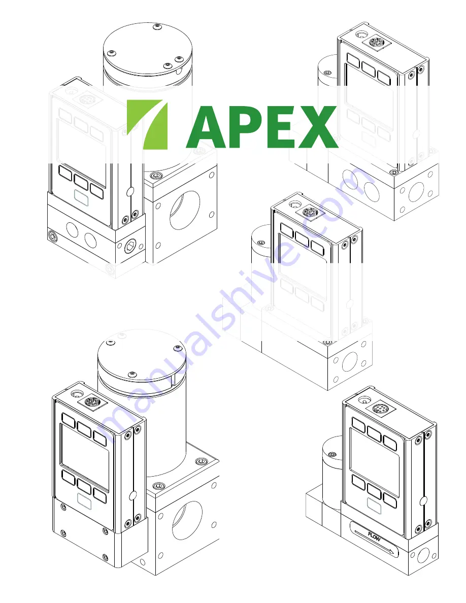
Page 5: ...ons The drawing to the right represents a typical configuration of a standard pressure controller Your pressure controller s appearance and connections may differ page 16 Backlight The monochrome display comes equipped with a backlight To toggle the backlight power press the bottom button on the front of your device For optional color TFT displays pressing this button will turn off the display to ...
Page 6: ...tal converter error LCK Front display is locked POV Pressure over range of device Mounting Pressure controllers do not require straight runs of pipe upstream or downstream Most pressure controllers can be mounted in any position including upside down Corrosive re sistant pressure controllers use media isolated sensors that must be tared after changing their orientation Caution Pressure controllers...
Page 7: ...n tape applied to the threads Warning It is not recommended to use pipe dopes or sealants on the process connections as these compounds can cause permanent damage to the controller should they get into the flow stream Connecting Your Pressure Controller Connect the controller so that the flow travels in the same direction as the flow arrow usually from left to right from the front of the device Wa...
Page 8: ...ssure and opens to decrease pressure Example Gas Supply Pressure Regulator Pressure Controller Process Flow Exit Port Downstream Valve Note Back pressure controllers include DS for downstream valve in their part codes Changing the Valve Orientation The valve position on your pressure controller can be switched in the field The controller must also be configured for either forward pressure control ...
Page 9: ...6 20 SAE ports or optional VCR compatible compression and VCO compatible fittings Process port sizes may change depending on the valve on your device Using Pressure Instruments with Liquids Many pressure devices may be used with chemically compatible liquids but a few warnings must be taken into account Water is more than 55 times more viscous than air This is important when sizing a pressure cont...
Page 10: ...c Output as the standard 0 5 Vdc analog output signal Pin 2 is normally a constant 5 12 Vdc More pinout configuration options begin on page 26 Analog Signals Primary Analog Output Signal Most devices include a primary analog output signal which is linear over its entire range For ranges that start at 0 Vdc a zero pressure condition is indicated at approximately 0 010 Vdc Full scale pressure is ind...
Page 11: ...rature or pressure After dropping or bumping the pressure controller After installing the controller in a different orientation Option Color TFT Display Instruments ordered with a color display are functionally the same as standard backlit monochrome instruments The color enables additional on screen information Multi Color Display Indicators GREEN Parameter labels and adjustments associated with ...
Page 12: ...rial commands page 20 or from an analog signal When the source is set to Serial Front Panel the controller will accept input from either the front panel or an RS 232 RS 485 connection Neither source is a slave of the other so the controller will accept the most recent command from either source When the source is set to Analog the device ignores serial setpoint commands and will prevent setpoint i...
Page 13: ...te Pressure controllers with upstream valves will control the outlet pressure Those with downstream valves can control upstream backpressure but these must be configured for this type of control Warning When changing the control loop you may need to adjust the PID settings for optimal stability and speed of response Adjusting the PD PDF or PD I Control Algorithms CONTROL Control Loop Loop Type You...
Page 14: ... I Increase the P gain in increments of 10 and then increase the I gain to fine tune Note Valve tuning can be complex Contact support if you need help page 16 Using a Control Deadband for Pressure Control CONTROL Control Loop Control Deadband The control deadband is designed to minimize the amount of gas exhausted and improve stability There is no active control within the deadband setting To turn...
Page 15: ...No Ramp If set to No Ramp the device will ignore the ramp rate just after powering on otherwise it will honor the ramp rate from a zero setpoint 0 Setpt determines whether the controller ramps when a zero setpoint has been given If this setting is set to No Ramp when given a zero setpoint the controller will immediately snap to the zero setpoint otherwise it will ramp at the selected rate Displayi...
Page 16: ...ibrated the device SW Firmware version Display SW color displays only Firmware version of the display Device Full Scale Ranges ABOUT Full Scale Ranges This displays the maximum calibrated range of available pressure readings Most will include only one type of pressure Devices equipped with an optional barometer will show absolute gauge and barometric pressures Manufacturer Information ABOUT About ...
Page 17: ...ful in smoothing fluctuating readings This menu changes the time constant of the geometric running average for pressure Values roughly correspond to the time constant in milliseconds of the averaged values Higher numbers generate a greater smoothing effect to a maximum of 255 ms Zero Band SETUP Sensor Zero Band The zero band threshold is an amount of pressure under which pressure values are displa...
Page 18: ...e Modbus address is the identifier that a computer or programmable logic computer PLC uses to distinguish your device from other devices when connected to a Modbus network Values of 1 247 are available for use Managing Setpoint with an Idle Modbus Connection If a Modbus connection is idle for a specified amount of time the device can be configured to set a zero setpoint or maintain the previous se...
Page 19: ...ers on On color displays press DIMMER or BRIGHTER to adjust the brightness level and move the brightness indicator left or right Display Rotation SETUP Display Display Rotation The device has the option of inverting flipping the screen upside down as configured in this menu Advanced Setup MENU SETUP Advanced The advanced setup menu contains settings and detailed information that are useful when tr...
Page 20: ...th any compatible terminal program over RS 232 PuTTy is a common option A USB port or COM port will not supply enough power to your device to function Please use another power source Configuring PuTTy 1 Download PuTTY from putty org and run the installer 2 Open PuTTY it will start on the Configuration screen 3 Click on the Terminal category The changes we make here will cause PuTTY to act like a n...
Page 21: ...time in milliseconds Example aw91 500 streams data every 500 ms Taring Taring pressure ensures that the gauge or differential pressure sensor reads zero Taring an absolute pressure sensor requires a barometer and aligns the absolute pressure sensor with the external barometric pressure For an accurate tare a gauge or absolute pressure sensor must be open to atmosphere while both ports of a differe...
Page 22: ... setpoints are sent by adding a hyphen for the minus sign New setpoint unit ID s floating point number setpoint Example as 15 00 setpoint of 15 00 PSIG Quick Command Guide Serial commands are not case sensitive In these examples the unit ID of the controller is a If you require more advanced serial communication commands please contact support page 16 Change unit ID current unit ID desired unit ID...
Page 23: ...e main menu select SETUP Sensor Engineering Units For more information see page 17 Pressure Readings Issue My controller won t reach its setpoint Action You must ensure that there is enough supply pressure to reach the setpoint If increasing the pressure doesn t help check to see if there is a clog Teflon tape can get stuck in the flow channel and block flow Make sure to clean out any loose Teflon...
Page 24: ...tarting on page 26 4 Make sure the COM number matches the one your software is using to connect to the pressure controller 5 On the external serial communications device computer PLC etc be sure that the pressure control handshaking settings are set as on page 20 Still experiencing issues Please contact support See Contact Information on page 16 Maintenance Cleaning This device requires minimal ma...
Page 25: ...orr mmHgA mmHgG mmHgD Millimeter of mercury at 0 C inHgA inHgG inHgD Inch of mercury at 0 C mmH OA mmH OG mmH OD Millimeter of water at 4 C NIST conventional mmH OA mmH OG mmH OD Millimeter of water at 60 C cmH OA cmH OG cmH OD Centimeter of water at 4 C NIST conventional cmH OA cmH OG cmH OD Centimeter of water at 60 C inH OA inH OG inH OD Inch of water at 4 C NIST conventional inH OA inH OG inH ...
Page 26: ...Vdc output signal 7 Power In 8 Ground common for power digital communications analog signals and alarms Caution Do not connect power to pins 1 through 6 as permanent damage can occur It is common to mistake pin 2 labeled 5 12 Vdc Output as the standard 0 5 Vdc analog output signal Pin 2 is normally a constant 5 12 Vdc Locking Industrial Connector Pinout Pin Function 1 Power In 2 RS 232TX RS 485 B ...
Page 27: ... Analog Out Analog Out RX or A Analog Out NC Analog Out 3 Ground Analog In NC NC NC NC NC 4 NC Ground NC NC NC Analog Out NC 5 Power In Ground Power In Ground Ground Power In Ground 6 NC Ground NC Analog Out NC NC NC 7 NC Power In NC Ground Power In Analog In NC 8 Analog In TX or B Analog In NC Analog In NC5 Analog In 9 Ground Ground Ground NC Analog Out 2 Ground Ground 10 Ground NC Ground Analog ...
Page 28: ...Analog Setpoint Input Analog Setpoint Input 5 Serial RS 232 TX signal Optional RS 485 B Serial RS 232 TX Signal Optional RS 485 B 6 Static 5 12 Vdc Optional Secondary analog output 4 20 mA 0 5 Vdc 1 5 Vdc 0 10 Vdc or basic alarm 0 5 Vdc Output Signal Optional 1 5 or 0 10 Vdc 7 Ground common for power digital communi cations analog signals and alarms Power in 8 Inactive Optional 4 20 mA primary out...