


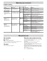

Maintenance and care
26
Regular testing
Regularly check that safety equipment is fully functional, at least once a year (e.g. BGR 232). Check that pressure-sensitive safety devices
(e.g. safety contact strip) are operating correctly every four weeks (see EN 60335-2-95).
Testing
Behaviour
Yes or No
Possible cause
Remedy
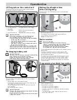
Power deactivation
Try to stop the door wing
while it is closing with
a 300 mm tall object.
The operator reverses
when it hits the object.
Yes
The force cut-off works
without limitations.
Leave all settings as they are.
No
Door incorrectly adjusted
Adjust door, call a technician.
Emergency release
Proceed as described
in the “Emergency release”
section.
The emergency release can
be easily actuated (pull once
and the operator releases).
Yes
All OK!
No
Operator forces the door
closed. Door and operator
mechanism is stressed.
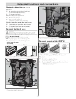
Adjust door CLOSE end switch or switch
on Backjump (DIP switch 6 ON).
Emergency release
defective.
Repair emergency release.
Door jammed.
Check door, see door owner's manual.
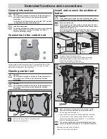
Safety contact strip,
if present
Open/close the door
and actuate the strip.
Adjust the behaviour
of the door, as set with
DIP switch 1, 2, or 3.
Yes
All OK!
No
Cable breakage,
terminal loose.
Check the wiring; retighten the terminal.
DIP switch adjusted.
Set the DIP switch.
Strip defective.
Decommission the system and lock
it to prevent reactivation.
Then contact customer service!
Photo eye,
if present
Open/close the door
and interrupt photo eye.
Adjust the behaviour
of the door, as set with
DIP switch 1, 2, or 3.
Yes
All OK!
No
Cable breakage,
terminal loose.
Check the wiring; retighten the terminals.
DIP switch adjusted.
Set the DIP switch.
Photo relay dirty.
Clean the photo eye.
Photo eye maladjusted
(holder bent).
Adjust the photo eyes.
Photo eye fault.
Decommission the system and lock
it to prevent reactivation.
Then contact customer service!
Maintenance and care
Disassembly
Important!
Observe the safety notices!
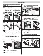
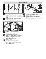
The sequence is identical to that described in the “Installation” section,
but in reverse order. Ignore the setting instructions.
Disposal
Observe applicable national regulations.
Warranty and customer service
The warranty complies with statutory requirements. The contact person
for warranties is the specialist retailer.
The warranty is only valid in the country in which the operator
was purchased.
Batteries and fuses are excluded from the warranty.
If you require after-sales service, spare parts or accessories, please
contact your specialist retailer.
We have tried to make the installation and operating manual as easy
as possible to follow. If you have any suggestions as to how we could
improve it or if you think more information is needed, please send your
suggestions to us:
Fax:
+49 (0) 7021 9447-25
E-mail: [email protected]
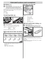
Miscellaneous