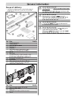
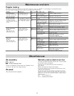
Aperto X-Box 550 Original Installation And Operating Manual Download Page 19

Operation/Use

19

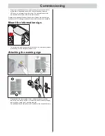
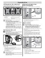
LED signals on the control unit

There are three LEDs on the control unit which provide information 
on the state of charge of the battery units.

1 Left 

LED 

fl

 ashes red 

Left battery box needs to be charged

2 Centre 

LED 

fl

 ashes green   

 Battery units are being charged via 
the solar module

3 Right 

LED 

fl

 ashes red 

Right battery box needs to be charged

Important information!
Under certain circumstances, the red LEDs may fl ash 
red even though the state of charge is suffi cient. 
To stop the fl ashing, reset the battery by doing the following:

•  Pull the plug of the solar module.
•  Slide both the batteries outside on the track to separate 

contact to the control unit.

•  After about 10 seconds, push the battery units back onto 

the control unit at the same time.

If the LEDs light up red even though there is suffi cient solar 
radiation reaching the CISfi x module, check the module for 
contamination and make sure that the lines and plugs are OK.

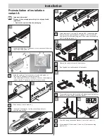
Recharging battery unit

Important information!
The battery units are constantly recharged by the Würth Solar 
CISfi x module when solar radiation is suffi cient. 
Alternatively, the battery units can also be recharged 
with a charger. Only use the original charger!

Charge the battery unit immediately when the LED (1) or (3) 

fl

 ashes 

on the control unit.
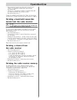
• 

Take the battery unit to be charged off the track.

• 

Plug the charger into the socket on the inner side of the battery unit 
to be charged, then attach the mains plug. 
(The left-hand battery pack is pictured, the right unit corresponds 
to the illustration.)

• 

Required charging time: 6–12 hours.

Important information!
Disconnect the charger from the mains power and the battery 
unit after no later than 12 hours.

Charge the battery in a standing position and not in the direct 
vicinity of heat sources.

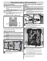
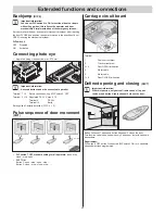
Setting the afterglow time 
of the LED lighting

The afterglow time of the LED lighting can be set to a value between 
10–120 seconds.

2

1

• 

Remove the rubber cover (1).

• 

Turn the knob (2) to the desired setting using a suitable tool 
(e.g. small PH0 x 3.0 mm screwdriver).

• 

Reattach the rubber cover (1).

Radio receiver

HomeLink-compatible!
If your vehicle is equipped with a HomeLink system 
(Version 7), our operator and radio receiver with 868.6 MHz 
are compatible. Another radio frequency (40.685 or 
434.42 MHz) must be used with older HomeLink systems. 
For information see: http://www.eurohomelink.com

• 

The local safety regulations for the system must be observed to ensure 
safe operation.

• 

Information is available from electrical utility companies, VDE 
(Association for Electrical, Electronic & Information Technologies) 
and professional associations.

• 

The operator is not protected against interference caused by other 
telecommunications equipment or devices (e.g. wireless systems 
which are being operated properly in the same frequency range).

• 

Replace the handheld transmitter unit's batteries if you experience 
reception problems.

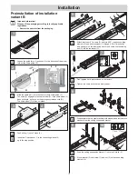
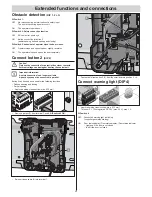
Programming handheld transmitter

2

4

3

1

5

• 

Take off the rubber cover (1).

• 

Press the Teach-in button (2).


– 1x for channel 1; the LED (3) lights up.


– 2x for channel 2; the LED (4) lights up.


– If no code is sent within 10 seconds, the radio receiver switches 

to Normal mode.


– Cancelling the teach-in mode: Press the Teach-in button (2) 

until no more LEDs are lit.

Summary of Contents for X-Box 550

Page 1: ...X Box 550 X Box 800 EN TRANSLATION OF THE ORIGINAL INSTALLATION AND OPERATING MANUAL 46725V001 422016 0 DRE Rev C_EN...

Page 2: ...afety instructions 18 Opening the door 18 Closing door 18 Emergency release 18 Control unit reset 18 Intermediate stop 18 Safety stop 1 power cut off 18 Safety stop 2 safety input 18 Overload protecti...

Page 3: ...in slip door you must install an emergency release release lock or Bowden cable that can be operated from outside Radio remote control The remote control must only be used for devices and systems in...

Page 4: ...x General Rated voltage 24 V DC Lighting Integrated LED lighting Operational temperature range 10 C to 45 C IP code IP 20 Working environmental emissions value 75 dBA operator only Operator 550 800 Ma...

Page 5: ...5 14 17 15 Item Name Quantity 14 Control unit with button and LED light field 1 15 Battery units left and right 2 16 Support rail centre housing is already installed on the track 1 17 Charger 1 Cautio...

Page 6: ...ty EMC interference resistance EN 60335 2 95 04 2011 General safety requirements for household and similar electrical appliances Part 2 Particular requirements for operators for vertically moving gara...

Page 7: ...tely mandatory if there is not a separate access point Slip door Pass door Built in pass door Caution If a slip door in set into the door a slip door safety device 20 must be installed Not included in...

Page 8: ...cessary before installation Ask a specialist retailer for advice All existing mechanical door locks must be removed or made non functional before beginning installation Check that the door runs smooth...

Page 9: ...disabled depending on the design of the door it could be possible to manually raise the door approx 50 mm To counteract this spring catches can installed to lock the door in addition to the operator T...

Page 10: ...3 1 1 2 4 Push trolley 1 onto C track 2 Insert two C track parts 1 in the connecting sleeve 2 up to the stop position C A B 90 D a c 90 b 1 2 3 4 5 6 V V 5 Attach tensioner 1 to chain 2 and turn it 9...

Page 11: ...2 1 3 1 1 2 4 Push trolley 1 onto C track 2 Insert two C track parts 1 in the connecting sleeve 2 up to the stop position a c 1 6 2 3 4 5 90 b 5 Attach tensioner 1 to chain 2 and turn it 90 Insert co...

Page 12: ...M VM 13 The operator can be mounted on the header S or on the ceiling D Measure the front of the centre of the door VM and mark on the door and on the lintel or ceiling Caution Wear safety glasses whe...

Page 13: ...cy unlocking cord N The carriage 1 is unlocked Tighten screw 8 on header fitting Slide the carriage 1 all the way to the front 3 with the connecting rod 2 If necessary loosen guide idler 4 Align door...

Page 14: ...t yet connect the XLR plug of the operator to the X Box Caution Note the wall thickness of the garage 1 72 m 23 Mark horizontal holes for the support rail on the wall drill 4 holes minimum height of 1...

Page 15: ...heck the following Have all mechanical door locks been removed Can the emergency release be activated from outside using a Bowden cable or release lock Important information When opening and closing t...

Page 16: ...he guide idlers Check whether the door opens and closes completely If this isn t the case then the running path must be adjusted Activate command initiator e g button handheld transmitter once Door op...

Page 17: ...imum of 112 storage locations for each radio receiver are available Mount the information sign N 46502V000 172006 0 OCE_Rev A The information sign concerning the function of the emergency release plea...

Page 18: ...ave a built in slip door or the garage does not have a separate entrance you must install an emergency release a release lock or Bowden cable that can be operated from outside see accessories instruct...

Page 19: ...esponds to the illustration Required charging time 6 12 hours Important information Disconnect the charger from the mains power and the battery unit after no later than 12 hours Charge the battery in...

Page 20: ...ess the handheld transmitter button whose code should be deleted in the radio receiver LED goes out The deletion procedure is ended Reattach the rubber cover 1 Repeat the procedure for all buttons and...

Page 21: ...the additional button Caution When actuating the button the drive must keep clear of the movement zone of the door and must have a direct view of it Important information Only necessary if an extra bu...

Page 22: ...e control unit Important information A safety connection is no longer available A photo eye cannot be connected in parallel Button 2 can be used as needed for the following functions Defined opening a...

Page 23: ...24 V max 0 1 A Terminal 9 DC 24 V Terminal 10 Earth Settings see Obstacle detection DIP 1 2 3 Pulse sequence of door movement DIP7 2 1 O N D I P 3 4 5 6 8 7 1x 1x 1x 1x STOP STOP DIP switch 7 OFF stan...

Page 24: ...opens the door completely Button 2 only opens the door partially if it is closed If the door is to be completely opened with button 1 or partially opened with button 2 pressing button 2 again closes t...

Page 25: ...plug to the solar module if necessary 1 2 3 4 5 6 7 Remove the four screws 1 on the front side Remove front housing 2 Caution First note the position of the plug and boards Make sure the board and plu...

Page 26: ...ective Decommission the system and lock it to prevent reactivation Then contact customer service Photo eye if present Open close the door and interrupt photo eye Adjust the behaviour of the door as se...

Page 27: ...o low Wipe force values and teach again Switch trigger incorrectly adjusted Adjust switch trigger see chapter Adjusting end switches Door incorrectly adjusted or defective e g spring shaft Have door a...

Page 28: ...he chain see chapter Installation Displays on radio receiver Malfunction Possible cause Corrective action All LEDs flashing All memory locations occupied max 112 Delete any handheld transmitters that...

Reviews: