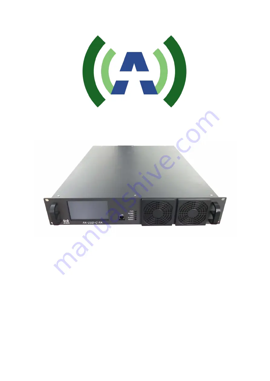
ANYWAVE
PA-U1D-C-FA
User Manual
Version 2.2 – September 25, 2019
Page 1: ...ANYWAVE PA U1D C FA User Manual Version 2 2 September 25 2019...
Page 2: ...sumed for its use The manufacturer makes no representations or warranties either expressed or implied by or with respect to anything in this manual and shall not be liable for any implied warranties o...
Page 3: ...re required from Anywave for all equipment returns Please direct all return inquiries to the Anywave Service Department at support_us anywavecom com providing the Sales Order number and Serial Number...
Page 4: ...ed as a general guide for trained and qualified personnel well aware of the dangers inherent in handling potentially hazardous electrical transmission equipment The installation operation maintenance...
Page 5: ...1 Product Appearance 6 1 1 Front Panel 6 1 2 Back Panel 7 2 Specifications 8 3 Control Interface 9 3 1 Web Interface 9 3 2 Local Touch Screen User Interface 14 3 2 1 Home Screen 14 3 2 2 A B Exciter I...
Page 6: ...stay constantly off when internal communication is abnormal LED_FWD The blue light will be on when RF_OUT has power output The blue light will be off when the RF button is turned off or the PA enters...
Page 7: ...g function The PA will enter the auto protection mode and there will be reduced RF output or even no RF output RF_OUT Connector N Impedance 50 Note RF_OUT must be connected with a load with proper imp...
Page 8: ...MER 32 dB VSWR 1 5 Shoulder Level 36dBc with pre correction ON Size 480mm W 89mm H 587mm L Note 1 The electrical interface characteristics are measured at the rated power Values may change 2 Operating...
Page 9: ...r s address bar to cause a login window to pop up The admin tier provides full status and control of the PA and is accessed with a username and password of anywavecom and anywavecom case sensitive Adm...
Page 10: ...e input of the PA or the output of the exciter without checking alarm s and ATT value setting first Otherwise once the alarm has been cleared you may have a much higher input level than needed and it...
Page 11: ...e amplifier The higher the value the more it attenuates the input level and therefore the output level If the default 0 stands for no attenuation at all 4 stands for 1dB in attenuation 8 stands for 2d...
Page 12: ...temperature alarm We recommend keeping those settings unchanged because they are pre set and optimized for the application before leaving the factory If they are changed without the permission of the...
Page 13: ...IP mask and gateway of the amplifier 2 If a user cannot recall the IP and therefore cannot log in remotely after making a change he can either reset the IP back to default 192 168 1 210 from its fron...
Page 14: ...nto 4 parts Title Bar left column Power Metering upper right Block Diagram middle right and Status Bar lower right as shown below Title Bar Shown in the picture above the Home button is highlighted in...
Page 15: ...B Exciter Icon Screen Dual Exciters Switching Screen Pressing the Exc A B icon will bring you to the Dual Exciters Switching Screen a shown below Manual Exciter Switchover As shown above Exciter A s...
Page 16: ...ter in the event of a problem with the on air exciter If neither of the exciters can be linked successfully i e the PA does not detect a valid RF output present from either exciter a window will pop u...
Page 17: ...ID of 81H Pressing the Exciter A or Exciter B button will bring up a window displaying the Exciter Channel Frequency and well as the TX System SNR and Upper and Lower Shoulder metrics Please note only...
Page 18: ...settings to the default values as shown below IP 192 168 1 210 MASK 255 255 255 0 GateWay 192 168 1 1 Set There is a Set button for each bar on this screen Pressing the Set button will lead to the co...
Page 19: ...o exit the setting mode Don t press Ok without entering a valid number otherwise the system will fill it with all zeros instead AGC Screen This screen is used to set the AGC Reference output power of...
Page 20: ...l navigate to the Amplifier Status Screens Temp Temperature of the amplifier V50 Reading of 50 V power supply of the amplifier Cur1 Device current Cur2 5 N A for this amplifier ATT The internal attenu...
Page 21: ...PA U1D C FA User Manual ACT PA U1D USR DOC V2 2 09 25 2019 Page 21 of 22...
Page 22: ...A U1D USR DOC V2 2 09 25 2019 Page 22 of 22 Anywave Communication Technologies Inc 300 Knightsbridge Parkway Suite 150 Lincolnshire IL 60069 Tel 847 415 2258 Fax 847 415 2112 Email sales_us anywavecom...