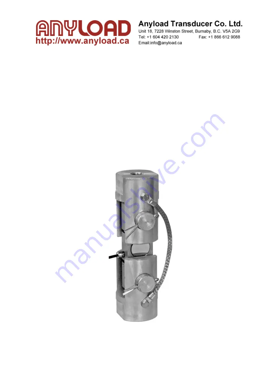
110BHM3
Weigh Module
Installation Guide
AL-Instruction-Weigh Module-110BHM3-12/13
Page 1 of 7
Page 1: ...110BHM3 Weigh Module Installation Guide AL Instruction Weigh Module 110BHM3 12 13 Page 1 of 7 ...
Page 2: ...Contents 1 Introduction 3 2 Replacement Parts Installation Tools 4 3 Installation Steps 4 4 Integral Installation 6 5 Dimensions 7 AL Instruction Weigh Module 110BHM3 12 13 Page 2 of 7 ...
Page 3: ...ign no threaded connection in between Self checking patented hole design provides high repeatability Multi directional movement Can withstand bigger bending and torsional force while providing a higher safety factor 1 Introduction AL Instruction Weigh Module 110BHM3 12 13 Page 3 of 7 ...
Page 4: ... load cell in one of the clevises and insert the pin Keep the load cell in the middle of clevis do not brush with the clevis As shown in the figure below 2 Replacement Parts Installation Tools 3 Installation Steps AL Instruction Weigh Module 110BHM3 12 13 Page 4 of 7 ...
Page 5: ...h the clevis As shown in the figure below Notice The angle of Cotter pin is 60 in principle The cotter pin must be okey at a time cannot be used again and again Step 3 Repeat step 1 and step 2 Install the second clevis to the other end of the load cell on straight pins and cotter pin As shown in the figure below AL Instruction Weigh Module 110BHM3 12 13 Page 5 of 7 ...
Page 6: ...en the screws to install the bonding strap As shown in the figure below 4 Integral Installation 5 Dimensions Jam nut must be tightened Jam nut must be tightened AL Instruction Weigh Module 110BHM3 12 13 Page 6 of 7 ...
Page 7: ...AL Instruction Weigh Module 110BHM3 12 13 Page 7 of 7 ...