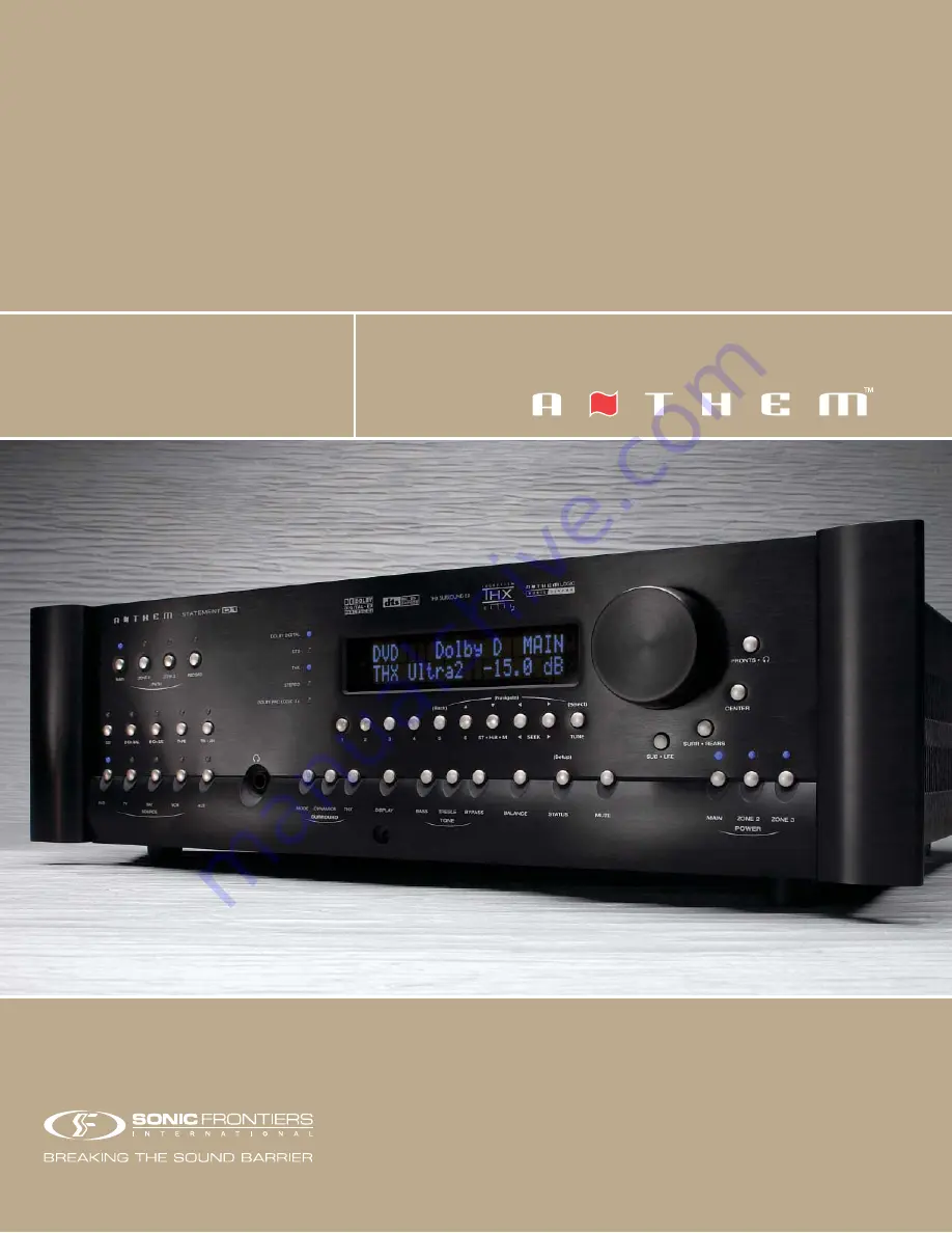
STATEMENT
D1
O P E R AT I N G M A N U A L
UPDATES:
www.anthemAV.com
S O F T W A R E V E R S I O N 1 . 1 x
™
Page 1: ...STATEMENT D1 OPERATING MANUAL UPDATES www anthemAV com S O F T W A R E V E R S I O N 1 1 x...
Page 2: ...MOVE COVER OR BACK NO USER SERVICEABLE PARTS INSIDE REFER SERVICING TO QUALIFIED SERVICE PERSONNEL RISK OF ELECTRIC SHOCK DO NOT OPEN WARNING 1 Read Instructions All the safety and operating instructi...
Page 3: ...or against them paying particular attention to cords at plugs convenience receptacles and the point where they exit from the product 12 Outdoor Antenna Grounding If an outside antenna or cable system...
Page 4: ...a fire or electric shock Never spill liquid of any kind on this product 17 Servicing Do not attempt to service this product yourself as opening or removing covers may expose you to dangerous voltage...
Page 5: ...Statement D1 to Amplifiers and Powered Subwoofer XLR 9 2 3 Speaker Placement 10 3 PANELS DISPLAYS REMOTE LAYOUT 11 3 1 Front Panel Layout 11 3 2 Front Panel Display 12 3 3 Rear Panel Layout 13 3 4 Re...
Page 6: ...0 25 5 8 3 Surround Modes for 2 0 Channel Source Material 26 5 8 4 Dolby Digital EX Pro Logic IIx for 5 1 Sources 27 5 8 5 DTS ES 27 5 8 6 THX Ultra2 THX Surround EX 27 5 8 7 Mode and THX Operation fo...
Page 7: ...7 4 1 Set Time Timers 41 7 4 2 Speaker Configuration 42 7 4 3 Listener Position 49 7 4 4 Speaker Level Calibration 50 7 4 5 Source Setup Presets 52 7 4 6 Adjust Input Levels 56 7 4 7 A D Audio Out Fo...
Page 8: ...heck that you have received everything in the Packing List below and report any discrepancies to your dealer as soon as possible Keep the invoice that you received from your authorized Anthem dealer a...
Page 9: ...s power line filtering and voltage regulation built in 1 2 3 IN USE NOTICES Use only the power supply cord with double insulation as supplied Disconnect the Statement D1 s power cord before connecting...
Page 10: ...he player s composite video out to Composite Video In DVD on the Statement D1 Audio Connect the player s digital audio output to Digital Audio In DVD on the Statement D1 Make sure your DVD player s se...
Page 11: ...g inputs can be set to Digital Signal Processing for bass management bass treble control time alignment and surround modes or Direct to bypass all digital stages Auto Dig uses the digital connection i...
Page 12: ...5 2 QUICK START continued 2 2 1 CD Player to Statement D1 CD Player EJECT Track 1 CD Player Audio Out R L...
Page 13: ...omposite Video Out S Video Out Audio Out R L Digital Out RCA Toslink Component Video Out Pb Y Pr DVD Audio Out Composite Video In Component Video In S Video In Vari Fixed L R Pb Pr Y Rear Panel of TV...
Page 14: ...d TV to Statement D1 2 QUICK START continued VCR Audio R L OUT IN OUT S Video Composite IN Video VCR EJECT Audio Out Composite Video In Component Video In S Video In Vari Fixed L R Pb Pr Y Rear Panel...
Page 15: ...8 Powered Subwoofer Level RCA Input XLR P O WER 2 2 4 Statement D1 to Amplifier and Powered Subwoofer RCA 2 QUICK START continued...
Page 16: ...Powered Subwoofer XLR To powered subwoofer WARNING Trigger Setup Suggestion If it is not necessary to have both amplifiers turned on when stereo sources are playing set triggers to turn on only the 2...
Page 17: ...N I E D I U G BACK SETU P 1 2 3 4 5 6 P OW ER 6 Ch A V M PAT H Dipole shown with null facing listening area Direct radiating see diagram below For accurate soundstage reproduction speaker size and dis...
Page 18: ...ics THX Options Surround Mode Level Bass Treble Balance Path Bass Treble Balance Display Brightness Setup Adjustment for Letters Numbers and Times 7 Surround Mode Headphone settings for Level Bass Tre...
Page 19: ...after the selected band is the preset station see section 5 4 2 2 FM mode Displays St when in stereo HB when Hi Blend is selected or Mn when in mono or mono is selected see section 5 4 2 3 Seek when...
Page 20: ...nable 17 Analog Audio 2 Channel XLR Input 2 Jacks 18 ZONE2 ZONE3 and REC Analog Audio RCA Outputs 19 3 Digital Audio Toslink Inputs Assignable 20 2 Digital Audio RCA REC Outputs 21 7 Analog Audio RCA...
Page 21: ...ss Treble Timers Display Brightness Navigation for Setup 25 Seek for FM AM Setting Adjustment for Surround Mode Balance Path Balance Navigation for Setup North South East West 26 Status FM AM Direct E...
Page 22: ...CA outputs For source components with Toslink outputs only use S PDIF TOS Any digital input may be assigned to any number of Sources that are set to Digital see section 7 4 5 Note An external RF demod...
Page 23: ...ee sections 5 7 5 8 7 4 2 and 7 4 5 4 2 4 ANALOG AUDIO OUTPUTS Balanced XLR connection offers the highest transmission quality particularly over long cable lengths because it rejects noise and hum pic...
Page 24: ...hen be separated again within the TV monitor by a comb filter resulting in some loss of video quality S Video S Video gives better video quality by transmitting color and brightness separately using a...
Page 25: ...Video In Vari Fixed L R Pb Pr Y Rear Panel of TV CATV In DVD Player Composite Video Out S Video Out Audio Out R L Digital Out RCA Toslink Component Video Out Pb Y Pr Satellite Receiver Composite Video...
Page 26: ...r I R RECEIVER inputs are re transmitted through the flashers 4 6 RELAY TRIGGERS If your other components have provisions for a trigger you can automatically turn them on and off together with the Sta...
Page 27: ...video source to other listening viewing rooms in your home The chosen Source can be either the same or different from the Source selected in other paths ZONE2 and ZONE3 each have outputs for a TV moni...
Page 28: ...without having to copy MAIN Note that DVD players do not normally provide a down mix for DTS material Note Even if L R Analog is connected keep the digital output from your DVD player connected to th...
Page 29: ...eset key To skip a preset set it to 87 5 FM or 530 AM ST HiB M If FM reception is weak switching a station out of stereo can reduce or eliminate unwanted hiss and noise Press ST HiB M repeatedly to cy...
Page 30: ...vel of all channels is then automatically reduced by 4 dB Mute When MUTE is pressed the audio of the selected Path is silenced or reduced see section 7 4 8 Press MUTE again or rotate the Master Contro...
Page 31: ...tereo PCM or Dolby Digital 2 0 source material Various surround modes can be applied to provide up to 7 1 channels of output These are described in depth throughout this section Each Source memorizes...
Page 32: ...amic movie listening experience that makes 2 channel movies sound more like what is experienced in a state of the art movie theater Again through extensive listening tests a very effective design was...
Page 33: ...und channels Pro Logic IIx Movie 7 1 Dolby Surround decoder for 2 channel movies and TV programs Pro Logic IIx Matrix 7 1 A matrix decoder that does not steer the image from one speaker to another Pro...
Page 34: ...soundtrack both in movie theaters and in your home theater as faithful as possible to what the director intended Movie soundtracks are mixed in special movie theaters called dubbing stages and are de...
Page 35: ...ailable as follows THX Cinema 5 1 to 7 1 output with 2 0 and 5 1 channel movies see overview that follows Processing Re Equalization Timbre Matching Adaptive Decorrelation if applicable When THX Cinem...
Page 36: ...y can be found on the THX web site at www thx com Bearing the THX Surround EX logo the Statement D1 will faithfully reproduce this technology in the home when in THX Surround EX mode The Statement D1...
Page 37: ...X Ultra2 Cinema 7 1 Re EQ Timbre Adp Decor ASA Cin DTS THX MusicMode 7 1 Timbre Adp Decor ASA Mus DTS THX Games Mode 7 1 Timbre ASA Gam DTS PLIIx Movie THX Cinema 7 1 Re EQ Timbre DTS ES Matrix DTS Ne...
Page 38: ...Timbre Matching Adp Decorrelation Output channels LF C RF RS LS Sub THX Cinema Processing Re EQ Timbre Matching Output channels All THX Games Mode Processing Timbre Matching ASA Game Output channels A...
Page 39: ...ecor ASA Music Output channels All THX Games Mode Processing Timbre Matching ASA Game Output channels All THX Surround EX Processing Re EQ Timbre Matching Output channels 6 1 LF C RF RS Rear LS Sub DT...
Page 40: ...X Processing for complete descriptions see section 5 8 6 Re Equalization De emphasizes treble Not applicable to THX MusicMode and THX Games Mode Timbre Matching Matches the sound character or timbre o...
Page 41: ...n be modified as can the time to rest when the display will dim see section 7 4 10 5 10 STATUS SETUP This button has two functions It displays information regarding current Software settings and modes...
Page 42: ...g MAIN near the top of the remote Note The Path Component keys do not transmit any commands to the Statement D1 or anywhere else They only determine where subsequent commands are sent For example if Z...
Page 43: ...can be entered as a four digit number For example to tune into 98 3 FM press and hold SELECT until the display shows blank 0 0 in the lower left corner then press 0 9 8 3 6 5 SLEEP TIMER Remote Contr...
Page 44: ...can not be programmed in the DVD Path Component key 6 8 2 SEARCHING FOR A CODE If a code for your component is not listed in Appendix B you can try the following 1 Turn the component on e g the TV 2 P...
Page 45: ...d command it might be better to program the learned command in Layer2 This means that when a taught key is pressed the original command functions as always and the learned command is accessed by press...
Page 46: ...ile it receives a signal from the Source Remote One long blink appearing during this step indicates a learning failure which could mean Bad Capture try again Memory Full delete another command Unlearn...
Page 47: ...priate path first and then enter the Setup Menu Front Panel Press and hold STATUS Setup for 3 seconds Remote Control Press and hold SUB LFE SETUP for 3 seconds 7 2 HOW TO NAVIGATE IN THE SETUP MENU Us...
Page 48: ...r 24 Hr Press the button to go to a CURRENT TIME 12 00 AM Press SELECT 12 will be highlighted in red Use the Master Control Knob or the buttons to set the current hour Press the button 00 minutes will...
Page 49: ...til you turn it off manually when you re done for the day Note If the Statement D1 is already on Timer On settings are ignored to ensure that Source and Volume are not changed when you are already lis...
Page 50: ...Press BACK to leave this submenu Note The Timer submenu setup procedure is the same for MAIN ZONE2 and ZONE3 Example 2 Change ZONE2 TIMER2 to come on Weekdays at 7 35 AM Enter the Setup section 7 1 Go...
Page 51: ...oom reflections When dipoles are selected as the SURROUND TYPE and or REAR TYPE their distance will automatically equal the greatest distance in menu 3 LISTENER POSITION see section 7 4 3 If you are u...
Page 52: ...recommended only for the Music configuration when using full range speakers set to Large together with the subwoofer 2 Sub or 2 Super Select when using both Subwoofer outputs This adjusts the level of...
Page 53: ...he crossover and sends a full range signal to the speaker If room acoustics cause cancellation in the crossover region sound can be improved by overlapping the Subwoofer setting with the settings of o...
Page 54: ...e played If you re using a sound pressure level meter set it to Flat or C weighting Filter Depth This is the amount of center frequency cut or reduction in volume in the subwoofer channel Frequencies...
Page 55: ...EL in menu 2 and press SELECT to display The loudest part of movie soundtracks is usually the bass that comes from the LFE track The Bass Peak Level Manager looks ahead at the bass signal and reduces...
Page 56: ...n 0 2 m increments Note Speakers set to Dipole in menu 2 SPEAKER CONFIGURATION will automatically have their distance set to equal the greatest distance of any other speaker see section 7 4 2 L Rear t...
Page 57: ...e master volume for the test noises and allows you reduce how much adjustment each channel will need based on how much output the Left Front channel has The setting depends on the sensitivity of your...
Page 58: ...uto Test Sequence Enter the Setup section 7 1 Go to 4 SPEAKER LVL CALIBRATION and press SELECT Use the buttons to set TEST SEQUENCE to Auto Press SELECT to start the automatic sequence As each speaker...
Page 59: ...ou want the Paths that are set to Always plus MAIN to change Source together with the single push of a Source button in any of these Paths Always Copy is not recommended if you want all Paths to have...
Page 60: ...o the same distance This is necessary when using Anlg DSP otherwise the processing occurs twice Anlg Dir Analog Direct not applicable to FM AM A D conversion and Digital Signal Processing are bypassed...
Page 61: ...ted the Statement D1 automatically uses the Cinema configuration if there is LFE in the source material and changes to the Music configuration at all other times Highly recommended when using the same...
Page 62: ...ss SELECT Press the button until you reach b AUDIO IN Dig RCA DVD and press SELECT RCA DVD will be highlighted Use the buttons to change to TOS1 sound will now be heard Press BACK to leave the submenu...
Page 63: ...erial Then as you switch through each highlighted Source you will hear that component play This lets you know that each component is connected to the Statement D1 and it also allows for easy comparati...
Page 64: ...rates Recording level is set by the input level in menu 6 see sections 5 2 1 and 7 4 6 This is also the signal processing rate for MAIN Neo 6 does not function when 2 Ch Anlg DSP Fs is set to 88 2 kH...
Page 65: ...n steps of 5 dB and for ZONE2 ZONE3 and HEADPHONE the range is from 70 0 dB to 10 0 dB in 1 25 dB steps To set a fixed output for ZONE2 or ZONE3 scroll MAX VOL past 10 0 dB to set LockOnVol and then s...
Page 66: ...me All Triggers When on Disabled all triggers remain off When on Enabled the trigger chart below is used to set conditions For custom installations RS 232 Ctrl uses external control over all triggers...
Page 67: ...o another To turn the input off use the buttons to change the to a Do this through the Front Panel since Remote Control commands are ineffective once an IR sensor is turned off Note If the Statement D...
Page 68: ...tc Choose from Bottom Mid or Top Main Z2 OS Color If the On Screen display of the Setup Menu appears unstable it could be that your monitor is not synchronizing to the blue factory default background...
Page 69: ...ter the Setup section 7 1 Go to 10 DISPLAYS TIMEOUT and press SELECT Press the button until you reach c MAIN OS POS N Bottom Use the buttons to change to Middle When finished press to go to another me...
Page 70: ...section 7 4 12 and will protect both USER and INSTALLER files from being changed by anyone who doesn t have the Password New saves will overwrite the previously saved file The Statement D1 will promp...
Page 71: ...eave the submenu and return to the main menu Example 3 Reload Factory Defaults Note The current time and FM AM Tuner presets will be retained Surround mode level balance bass treble adjustments sectio...
Page 72: ...sword if there is one Go to 12 LOCKOUT PASSWORDS and press SELECT Press the key to go to b SET USER PASSWORD Press SELECT You will be asked to enter a four digit number Use the 0 9 keys to do so If yo...
Page 73: ...is service 8 3 SOFTWARE UPDATING VIA YOUR COMPUTER AND THE INTERNET To update the Software through your computer you will need the following Access to the Internet Serial cable straight wired with one...
Page 74: ...ring a power failure 8 Using the serial cable connect your computer to the Statement D1 via the RS 232 port on the rear panel Updating does not require moving the Statement D1 or disconnecting it from...
Page 75: ...o 6 THX Cinema For DTS sources THX 4 0 THX Off THX 4 1 THX Cinema THX 4 2 THX Ultra2 Cinema THX 4 3 THX MusicMode THX 4 4 Neo 6 THX Cinema THX 4 5 THX Games Mode THX 4 6 PLIIx Movie THX 4 7 PLIIx Movi...
Page 76: ...19 0039 Pioneer 0166 Portland 0019 0039 0092 Prism 0051 Proscan 0047 Proton 0178 0466 Pulsar 0017 0019 Quasar 0051 0250 0165 RCA 0047 0051 0093 0019 0090 0135 1047 1147 1247 1347 Radio Shack 0047 0154...
Page 77: ...mbos American High 0035 TV 0051 Brocksonic 0002 0294 Colt 0072 Curtis Mathis 0035 TV 0051 Daewoo 0278 Emerson 0002 0294 0479 Funai 0000 GE 0035 TV 0051 0060 TV 0047 0048 TV 0093 0240 Hitachi 0035 TV 0...
Page 78: ...7 0220 0099 Sansui 0029 Sony 0243 0170 0291 Technics 0229 Victor 0273 Wards 0027 Yamaha 0097 0094 Stereo Tuners or Receivers ADC 0531 Adcom 0616 Aiwa 0158 0189 0121 0405 Akai 0224 Capetronic 0531 Carv...
Page 79: ...72...
Page 80: ...Analog to Digital Converters AKM AK5394A Analog to Digital Conversion S N Ratio at digital Rec output IEC A Filter 103 dB Input Receiver AKM AK4112A Processor dual Motorola 56367 at 150 MHz Sample Ra...
Page 81: ...uts 107 dB Analog DSP Inputs at 24 48 or 24 96 101 dB Digital Inputs at 24 48 or 24 96 104 dB ZONE2 and ZONE3 Paths Frequency Response and Bandwidth 20 Hz to 20 kHz 0 0 1 dB 3 Hz to 140 kHz 0 3 dB THD...
Page 82: ...it no parity bits flow control RTS CTS NONE Trigger Outputs Polarity tip positive sleeve negative Max Current at 12 VDC 50 mA Triggers 1 2 200 mA Trigger 3 Sequential Delay 250 ms POWER REQUIREMENTS S...
Page 83: ...onsibility for any damage occurring to a product that is shipped in any type of carton and packing material other than the original carton and packing material To receive service under warranty an acc...
Page 84: ...THE BIG PICTURE FRONT PANEL...
Page 85: ...THE BIG PICTURE REAR PANEL...
Page 86: ...T U R E D I N N O R T H A M E R I C A A n t h e m c a n b e r e a c h e d f r o m 9 0 0 a m t o 5 3 0 p m E S T b y p h o n e 905 362 0958 o r 2 4 h o u r s a d a y b y f a x 905 564 4642 w w w a n t...