K Connector
â
Microstrip to K Female
Sparkplug Connector
Part Numbers:
K102F/K102F-HT
1. Tools And Materials
The following tools and materials are needed to install
the K102F/K102F-HT Flange Mount Connector in a
mounting hole on a housing. Equivalent tools may be
used if the recommended tools are not available.
Name
Vendor and Model/Part
Number
Hot Plate
H2155,
Micro Hot Plate,
Thermolyne, Baxter Scien-
tific Products
Step Drill Kit
01-104 or 01-108
Anritsu Co.
Torquing Tool
01-105A
Anritsu Co.
Support Bead
Holding Fixture
01-103
Anritsu Co.
Solder, 62% tin,
0.50 mm diameter
rosin core
SN62
Kester Co.
or AuSn
Rosin Flux
135, Kester Co.
Cleaning Fluid
isopropyl alcohol
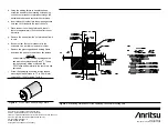
2. Machining Dimensions
Machining dimensions for the mounting hole required
for installation of the microstrip to K female flange
mount connector are provided in Figure 5 on the re-
verse side.
CAUTION
The four holes shown in Note 2 of Figure 5
must be concentric within
±
0.038 mm. If they
are not, connector performance will be de-
graded. To make this required concentricity
easier to achieve, custom-made drill-bit kits,
Models 01-104 and 01-108, are available from
Anritsu.
3. Fabrication Instructions
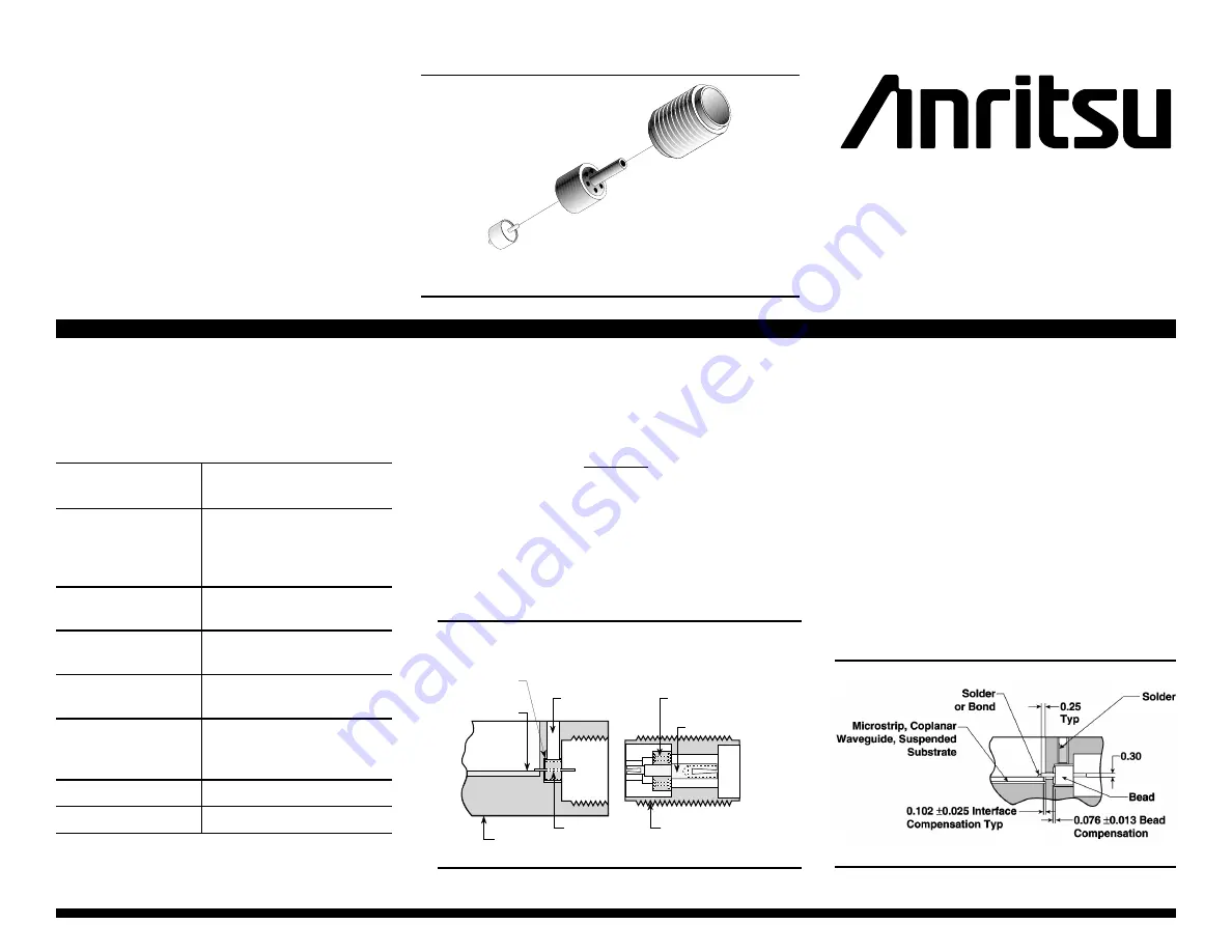
Fabrication instructions for the sparkplug connector
assembly are provided below. Figures 1 and 2 identify
the connector parts. Refer to these figures while per-
forming the following steps.
a. Install the microstrip into the housing. Refer to
Figure 3 for dimensional tolerances around the
glass bead.
b. Set the hot plate to 200
° ±
10
°
C for SN62, or 310
°
±
10
°
C for AuSn solder.
c. Flux the glass bead and insert it, long-end first,
into the 01-103 Glass Bead Holding Fixture (Fig-
ure 4).
Backside
Interface
Center Conductor
Support Bead
Soldering
Access Hole
Center Conductor
Glass
Bead**
Housing
Sparkplug
Microstrip
Figure 2.
K Connector Sparkplug Assembly
Figure 3.
Glass Bead Installation
Glass
Bead**
Center Conductor
and Support
Bead Assembly
Sparkplug
Figure 1.
Sparkplug Connector
(** not supplied)


