Anest Iwata MSU-113 N Use And Maintenance Manual Download Page 1

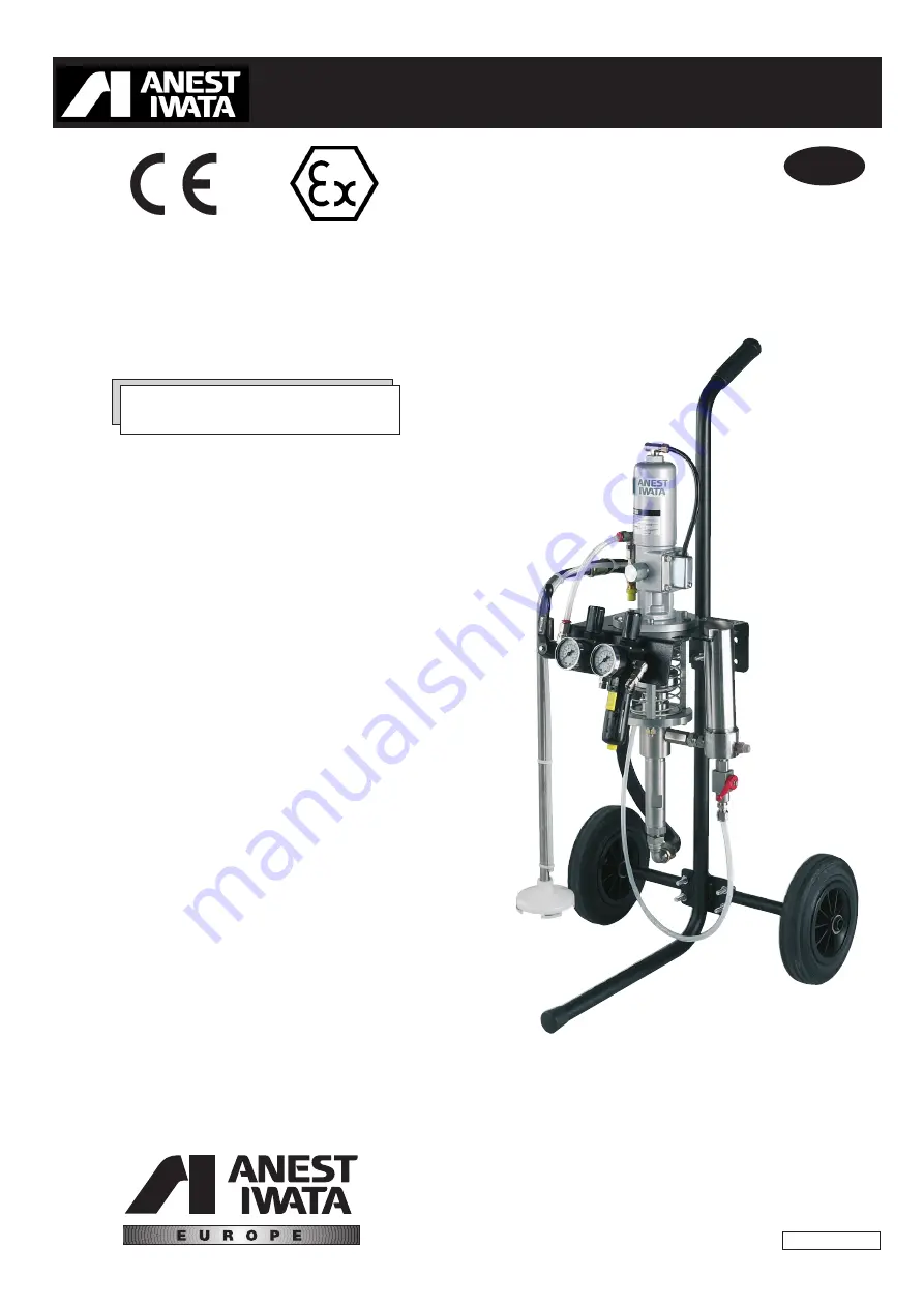
Use and maintenance manual

MUL

MUL

TI SPRA

TI SPRA

Y UNIT

Y UNIT

GB

ME113NERev.13

MSU-113 N

MSU-113 N

ANEST  IWATA Europe s.r.l.

46, Corso Vigevano 
10155 Torino - Italia 
Tel. +39 011-24 80 868 
Fax +39 011-85 19 44

www.anest-iwataeu.com
e-mail: [email protected]

Summary of Contents for MSU-113 N

Page 1: ...UL MULTI SPRA TI SPRAY UNIT Y UNIT GB ME113NERev 13 MSU 113 N MSU 113 N ANEST IWATA Europe s r l 46 Corso Vigevano 10155 Torino Italia Tel 39 011 24 80 868 Fax 39 011 85 19 44 www anest iwataeu com e...

Page 2: ...r l staff members use their knowledge and competence to provide their cus tomers with high quality reliability and constant innovation Our activities as the ones of other companies are in compliance w...

Page 3: ...22 5 7 Improper and dangerous uses 22 5 8 Procedure to discharge the pressure 23 6 MAINTENANCE AND INSPECTION 24 6 1 General notes 24 6 2 Safety rules during maintenance 24 6 3 Recommended programmed...

Page 4: ...94 9 CE Directive The operations provided with this symbol must be carried out by qualified staff having a specific com petence concerning the safety of the areas with an explosive atmosphere We reco...

Page 5: ...rding to the Essential Safety Requirements of the Machinery Directive 98 37 CE Moreover the units are planned and built in compliance with the Essential Safety Requirements ESR of the Enclosure II of...

Page 6: ...GINAL CONFIGURATION OF THE EQUIPMENT MUST NOT BE CHANGED AT ALL On receiving the equipment check that The supply corresponds to the order specifications In case of non compliance inform immediately ou...

Page 7: ...repair operations carried out by the customer or by a third party either THE WARRANTY DOES NOT COVER Damage or breakdown caused by improper use or assembly Damage or breakdown caused by the use of sp...

Page 8: ...IS ADVISABLE THAT THE STAFF IN CHARGE OF HANDLING THE EQUIPMENT WEAR PRO TECTIVE GLOVES AND SAFETY SHOES WARNING WHILE LIFTING OR HANDLING THE EQUIPMENT OR ANY OF ITS COMPONENTS CLEAR THE WORKING ARE...

Page 9: ...LOW THE INSTRUCTIONS ON THE PACKAGING BEFORE HANDLING AND OPENING IT HANDLING BY MEANS OF CART HANDLING BY MEANS OF TROLLEY 1 4 Temporary storage During transport and storage make sure the temperature...

Page 10: ...13 N MULTI SPRAY UNIT MSU 113 N MODEL WITH PAINT FILTER Pump type PP 7131N on cart with air regulator gun spraying adjustment suction pipe delivery and suction paint filter fluid recirculation MSU 113...

Page 11: ...ession ratio 13 1 Inlet air pipe fitting G1 4 Outlet air pipe fitting G1 4 Material inlet pipe fitting G1 2 Material outlet pipe fitting G1 4 Maximum working pressure 6 8 bar Max fluid pressure 88 bar...

Page 12: ...t Moreover all the other necessary environmental safety measures for example the possible gas and residual dust decontamination etc must be taken SAFETY VALVE An 8 bar calibrated safety valve is insta...

Page 13: ...d paints and water based pains with low or average viscosity To use the equipment with special products ask for the approval of the manufacturer Moreover the technical features of the unit must be ada...

Page 14: ...ated suction tube and rod The packing can be adjusted The motor s straight and alternate movement creates an equivalent movement in the pumping unit A system of valves allows the simultaneous suction...

Page 15: ...completed To connect the multi spray unit and the gun use the antistatic type pipeline The equipment must be installed by a specialized and authorized staff In any case follow the instructions below...

Page 16: ...F 1 5 MM2 ONE END OF THE CABLE MUST BE EARTHED WHILE THE OTHER MUST BE CONNECTED TO THE COVER OF THE PNEUMATIC MOTOR PACKING 4 4 Cautions 1 Operate the pump with air filtered by means of an air filter...

Page 17: ...ve C CLOSED OPEN Pressure regulator G Stop position Ball valve E Operating position Air inlet G 1 4 Adjusting cup D Upper packing Suction hose A Paint inlet G 1 2 Ground cable Paint outlet G1 4 Paint...

Page 18: ...ation valve C CLOSED OPEN Pressure regulator G Stop position Ball valve E Operating position Air inlet G 1 4 Adjusting cup D Upper packing Suction hose A Paint inlet G 1 2 Ground cable Paint outlet G1...

Page 19: ...with them It is not to be held responsible for any carelessness during the pump use either If the system is used improperly it could be broken causing serious damage Use the multi spray unit for prof...

Page 20: ...until stopping the cleaning liquid outflow and the pump movement NOTE The failure to observe this point as well as an improper initial adjustment of the packing might reduce its duration 8 Once the p...

Page 21: ...the tank decreases the pump might suck some air Increase the level of paint c Do not drag the pump by pulling it by the pipes d Do not spray towards the eyes or towards other people CAUTIONS EMERGENCY...

Page 22: ...ke some serious injuries WARNING IF SPARKS OR AN ELECTRIC DISCHARGE ARE PERCEIVED INTERRUPT IMMEDIATELY ALL PAINTING OPERATIONS DO NOT USE THE SYSTEM UNTIL THE CAUSE OF THE PROBLEM IS IDENTIFIED Keep...

Page 23: ...gun tightly and lean it against the metal vessel with the paint Remove the safety catch of the multi spray gun trigger and gently pull the trigger to release the pressure inside the multi spray pipe...

Page 24: ...uring maintenance The main rules to follow during maintenance interventions on the unit are 1 Disconnect the pneumatic supply before replacing any component 2 Do not wear rings watches chains bracelet...

Page 25: ...ece 32 3 Loosen and remove the air cylinder 1 4 Remove the split pin 28 5 Remove the adaptor 23 unscrew the stopper 15 and remove the spindle set B from the main body 27 6 Loosen the cap nut 2 and rem...

Page 26: ...operation IMPORTANT 1 Put grease on all the moving components o rings and packing located inside the air cylinder 2 Make sure the interlock piece is inserted in the rod chink 3 Make sure the block is...

Page 27: ...dle set 7 NOTE the following components are assembled on the stopper stopper 12 washer 13 Y packing 14 O ring 6 2 Assemble the following components on the spindle set 7 washer 5 washer 3 quantity 2 pa...

Page 28: ...28 3 Insert the spindle set 7 in the main body 27 4 Screw the stopper 15 in the main body 27 5 Screw the adaptor 29 and the spindle set 7 6 Insert the split pin 28 7 Screw the air cylinder 1...

Page 29: ...pring 35 interlock end piece 33 interlock piece 32 9 Insert the washer 34 in the main body 10 Screw the cap 36 to the main body 11 Insert the seat block A in the main body and screw the four bolts 26...

Page 30: ...the exhaust cover 23 to the main body The ground cable 60 is anchored to the exhaust cover by means of the cross pan head setscrew 24 6 8 Pneumatic motor disassembly from the fluid pump set 1 Keep th...

Page 31: ...upper valve holder set 53 4 Remove the V packing male adaptor 48 the lower V packing 49 the lower V packing female adaptor 50 and the ball 51 5 Unscrew the thinner cup set 42 from the suction body 40...

Page 32: ...omponents and replace them if necessary 6 11 Fluid pump set re assembly Reverse the above mentioned procedure bearing in mind the following points 1 Adjust the lower packing in order to obtain a smoot...

Page 33: ...be 54 with the running pump Air pressure 0 5 bar This procedure allows a further reduction of the adjustable packing wear 6 13 Tests to be carried out after the re assembly 1 The pump must start with...

Page 34: ...e gun filter c Clogged nozzle c Remove the nozzle and pull the trigger c If the paint flows out it means of the gun that the nozzle is clogged Free the nozzle with a steel pin and clean it with a non...

Page 35: ...eplace them if they are worn out b Damaged or dirty valves or balls b The pump does not stop b Disassemble and clean them Replace them if they are too damaged c Worn out gun nozzle c Replace it d The...

Page 36: ...ge from the paint a Loosened cylinder a Tighten it filter model with paint filter 11 Air leakage from the air a Worn out or damaged O rings ref Page 38 a Replace them motor components 16 20 b Worn out...

Page 37: ...adaptor 1 13 Washer 2 45 V packing 4 14 Y Packing 2 46 V packing male adaptor 1 15 Stopper 1 47 Nut 1 16 O ring 1 48 V packing male adaptor 1 17 Block 1 49 V packing 4 18 Guide plate 1 50 V packing fe...

Page 38: ...38 Plunger pump set type PP7131N...

Page 39: ...3 8 M 1 8 Two way ball valve G1 4 FF 1 9 Hose joint R1 4 M M8x6 1 10 Swivel joint R3 8 M G3 8 F 1 11 Fluid nipple G3 8 M G1 4 M 1 8 3 DRAIN VALVE SET For MSU 113 N model without paint filter Pos Descr...

Page 40: ...or set 1 1 Quick joint B P 1 4 M 90 1 2 Ball ball valve with hexaust hole 1 3 Nipple G1 4 MM 1 4 Air regulator G1 4 FF 1 5 T Joint MFM G1 4 1 6 Nipple Rc1 4 M G1 4 F 2 7 Air regulator with filter G1 4...

Page 41: ...3 N model with filter For MSU 113 N model without paint filter Pos Description Quantity A Suction hose set 1 1 Suction hose 1 2 Air hose 1 3 Complete cover set 1 3 1 Cover M15x1 1 3 2 Filter 50 MESH 1...

Page 42: ...AND PLATE FOR MSU 113 N MODEL WITH PAINT FILTER FOR MSU 113 N MODEL WITHOUT PAINT FILTER Pos Description Quantity 1 Frame set 1 2 Wheel 2 3 Split pin 4 4 Washer 4 5 U bolt 1 2 2 6 Pump base 1 7 U bolt...

Page 43: ...pment from the energy sources Remove all residues and deposits from the pump Cover the equipment with a waterproof tarpaulin 9 2 Dismantling If for any reason the pump is to be dismantled some importa...

Page 44: ...com ANEST IWATA Scandinavia g rdesv gen 6C 433 30 PARTILLE Sweden Tel 46 0 31 340 28 60 Fax 46 0 31 340 28 69 info anest iwata se www anest iwata se ANEST IWATA France 25 rue de Madrid 38070 St Quent...

Reviews: