


AMD5x Passive Infeed Unit and AMD5x Servo Drive - User Guide
ANCA MOTION
D-000129 Rev 09
90
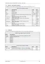
X20
– IO Interface for the Associated Pin Assignment
6.7.1
Polarisation is provided for each mating connector-plug via the inclusion of factory fitted Coding Keys (Red) on
pins 12 and 13 of the IO Interface connector-header (X20).
For AMD5x Drives supplied with the optional Connector Kit, the two supplied connector-plugs are also provided
with the associated pin keys removed. These connector-plugs have a Spring Cage format and support the
termination of a wire gauge range of 20
– 26 AWG with a wire strip length of 8 mm, or ferrules with a cross
sectional area range of 0.25
– 0.50 mm
2
. Ensure the correct wire strip length is used so that the wire insulation is
located within the body of the Spring Cage connector, to minimise short circuits between adjacent wires on the
connector. It should be noted that the connector format only supports connection of a single wire per pin.
It is recommended that the customer fits the wires/cables assemblies to the connector-plug
prior
to connection to
the User Interface.
Functional isolation (between SELV circuits) is provided by the IO Interface from the rest of the Servo Motor Drive
system.
Two customer supplied external voltage references are required for the use of the Digital Input and Digital Output
subsystems.
An internal power supply supports all other IO Interface functions (including the Analog subsystems).
External Voltage References
6.7.2
The IO Interface requires the use of two external voltage references for operation of specific subsystems:
VREF24 V: X20/13: Digital Input, General Purpose Digital Output
VREFHS: X20/1: High Speed Digital Output
The VREF24 Vdc Positive Reference has a nominal value of +24 Vdc, is used for both the General Purpose
Digital Output and Digital Input subsystems, and must be connected for correct subsystem operation.
The VREFHS Positive Reference has a nominal range of +5 to +24 Vdc, is only used for the High Speed Digital
Output subsystem, and must be connected for correct subsystem operation.
A common Positive Reference of +24 Vdc can be applied to both VREF24 Vdc and VREFHS when the High
Speed Digital Output subsystem requires an interface drive level of +24 Vdc.
A common Negative Reference of 0 Vdc is provided across all subsystems.
All Positive and Negative References are functionally isolated (between SELV circuits) from the rest of the
AMD5x Drive system. It should be noted that a common Negative Reference (0 Vdc) could be used between the
AMD5x Drive (system) and the IO interface, but this could lead to noise related performance issues on some
subsystems.
Distribution
6.7.3
The IO Interface provides for effective termination of the external Positive References, the common Negative
Reference, and the shields of interconnecting cables.
The distance between the IO Interface Front Panel Connectors and any associated Distribution Terminal Strips
should be minimised.
It should also be noted that the IO Interface provide common Negative Reference pins for the Digital Output,
Analog Input and Analog Output subsystems.
Summary of Contents for AMD5x Series
Page 12: ......


