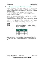
CO Clear
User Manual
Int. Approved
Document ref: ACO-810-28
October 2018
Page 10 of 24
Copyright © 2006 Analox Ltd. All Rights Reserved.
Commercial in Confidence
6
Option available
6.1
AC supply models
A mains powered Analox CO
Clear
is pre-wired with a mains cable, fitted with a plug suited
to the destination country. Where internal plug fuses are fitted, these are 3 Amp. Ensure
that the unit is connected to the correct supply voltage (i.e. 110 or 230V AC). Where no
fuse is fitted in the plug, the instrument should be powered from a 3 Amp fused outlet.
The Analox CO
Clear
is fitted with an internal fuse, which is rated at 500mA.
6.2
DC supply models
A DC powered Analox CO
Clear
require a DC supply in the range 9-24V DC. A 2m cable is
factory fitted to the instrument. The DC supply should be connected to this cable as
follows:
1.
Blue wire negative (0Volts)
2.
Red wire positive (+9-24Volts)
6.3
Alarm repeaters
The Alarm Repeater has four status indicators and a Mode button, which mimic the button
and indicators on the main Analox CO
Clear
enclosure.
An 8 metre, 8 core cable is pre-wired to the Analox CO
Clear
on units to be fitted with an
alarm repeater. This ensures that for a basic installation, there is no need to dismantle the
Analox CO
Clear
main unit. A maximum of three repeaters may be fitted in a daisy chain
configuration.
To connect and disconnect a “Quick Connect” Repeater:
Disconnect the power supply from the Analox CO
Clear
.
Insert the connector on the end of the cable into the socket on the base of
the Alarm Repeater.
Restore power to the Analox CO
Clear
. Press the mode button on the
repeater once and ensure that the four indicators flash. Note that in the
presence of a genuine alarm, the test feature is disabled.
6.4
Alarm relay output models
You may have ordered your Analox CO
Clear
with a relay. The relay contacts are ‘Volt
-
Free’ single pole Changeover, rated 250vAC/30vDC 2 Amps. The relay is non
-latching. This
means the relay will only initiate when gas is present. As standard the relays are setup in
a Fail-Safe configuration. This means that the relay is energised during normal operation.
Please note that on power up the relay is only energised after the 40 second warm-up
period. See Figure 1 for details of how the relay should be connected.
Summary of Contents for CO Clear
Page 2: ......


