DBS9900 User’s Manual
DBS9900 Clock
7-17
82-28993 Revision 01
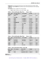
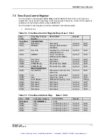
D[04]
is the
Lock Detect
signal from the PLL. This output is available when
F[5:3]
is
programmed to
1h
in the function latch.
D[04]
is set high by the PLL when the absolute phase
error is less than 15nsec for at least 3 or 5 consecutive phase detector cycles (3 or 5 * 1/Fpd =
60
µ
sec or 100
µ
sec), depending on what
R[19]
is programmed to.
R[19]
should be programmed
low, which forces three phase detector cycles to be used to determine frequency lock.
FO_LD
(
D[04]
) will go low if the phase detector error exceeds 30nsec. for more than one phase detector
cycle. It is set to a low state when the charge pump is tri-stated or the PLL is powered down (
F[2],
F[18]
). This is a Read Only signal designed to indicate phase lock.
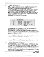
7.10 High Speed Divider Data Register
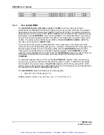
The
HSDIV Register
(0x14, BASE + 0x18 = 7h) R/W
is a 4 bit register designed to program the
HSDIV
divider. To access this register, The software driver writes to the control bits located in
BASE +
0x18 = 7h
of the VXI FPGA. This register instructs the FPGA that the next register writes
the
HSDIV Register
at
0x14
.
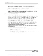
The hardware transfers data to the 6 bit ECL counter. When the
PLL_EN
,
INTREF
is active high
and
REFSEL
,
FREQSEL0
are low the
HSDIV
divider will clock this data into the counter on the
rising edge of the clock when
! COUT
(terminal count) drives S1 low. The counter will count down
toward zero on each clock. Once the count reaches zero, the terminal count will stay low for one
clock cycle and will re-load the data into the counter on the clocks next rising edge. When the
divider is programmed to count by two, the output is a square wave and is sent directly to the time
base frequency selector MUX. For counts greater than two, the terminal count is routed to an
external flip-flop and then on to the time base frequency selector. This flip-flop will only toggle on
the rising edge of terminal count, thereby making the output wave form a 50% duty cycle square
wave.
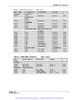
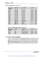
The
HSDIV Register
should be initialized to the following state:
•
All bits read back low when the board is initialized.
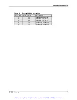
The data will read back in the following format:
Artisan Technology Group - Quality Instrumentation ... Guaranteed | (888) 88-SOURCE | www.artisantg.com


