


DBS9900 User’s Manual
7-4
DBS9900 Clock
82-28993 Revision 01
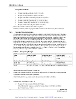
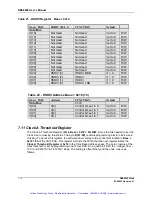
50ns min. hold
50ns min. Clk to Load
50ns min. clk pwd
50ns min. clk pwd
50ns min. setup
PLL_CLK
PLL_DATAI
PLL_LE
PLL_CE
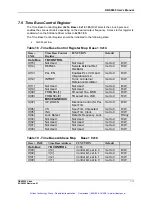
7.6.1
TIME BASE RESET
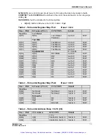
The time base registers should all be set to their default settings as shown in the default column
of each register upon power up, Hard Reset, or Soft Reset.
Since the LMX2306 PLL is a serial load device it will be up to the software driver to initialize the
internal registers to their default state as defined in the default columns of the PLL registers (
R-
COUNTER, N-COUNTER, FUNCTION LATCH
). Notice that the
FUNCTION LATCH
should be
written twice in order to reset internal counters.
F[1]
set high resets the counters, and
F[1]
set low
starts the counters counting in synchronism. The
FO_LD
line should be configured (
F[5:3] = 1h
)
to output Lock Detect.
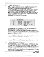
7.6.2
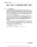
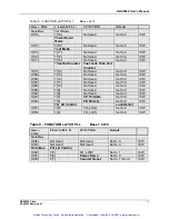
PLL R-COUNTER
The
R-COUNTER
(0x14, 0x16, Base + 0x18 = 0h) R/W
is a 21 bit control word that is
transmitted to the DBS9900 VXI Interface FPGA in one 16-bit and one 5-bit write. The software
driver writes to the control bits located in
0x18 = 0h
of the VXI FPGA. This register instructs the
FPGA that the next two register writes,
0x14
and
0x16
will be directed through a parallel to serial
shift register to the
R-COUNTER
. The control word
C[4:1]
, is concatenated to the end of the bit
string, and controls the register inside the PLL that is to be loaded upon completion of the serial
transfer. The MSB’s of the
R-COUNTER
are to be loaded into
BASE + 0x14
. The five LSB’s are
transmitted to
BASE + 0x16
. The 21-bit serial shift register (internal to the LMX2306) is loaded
MSB first, via the data input on the rising edge of the clock when the Latch Enable (
PLL_LE
)
goes low.
Loading is complete after 21 rising edges of the clock. The internal register is latched on the
rising edge of
PLL_LE
. The
R-COUNTER
divides the reference clock down to the phase detector
comparison frequency (
Fpd
). The legitimate division ratios for the
R-COUNTER
are 3
≤
R
≤
16383. The DBS9900 uses a fixed 10MHz reference oscillator so the
R-COUNTER
should be
programmed to a divide ratio of
R
= 200d = c8h for
Fpd
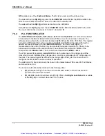
= 50kHz. The data format for the
R-
COUNTER
is shown in the table below.
R19
determines the lock detect precision.
When
R19
is set low, the PLL decides that it is only in frequency lock after three consecutive
reference clock cycles where the reference and VCO input edges are within 15nsec of each
other. If set high, the PLL decides that it is in frequency lock after five consecutive reference clock
cycles.
R[18:15]
set test modes used by the manufacturer and should be set low.
R[14:1]
are the bits of the
R-COUNTER
where
R14
is the MSB and
R1
is the LSB.
Artisan Technology Group - Quality Instrumentation ... Guaranteed | (888) 88-SOURCE | www.artisantg.com