background image


OCTO

²

 / QFX402 


PAGE 44


APPENDIX A: PROGRAMMER'S GUIDE 

A-1: INTRODUCTION 

If you need to use your own Software Control program 
from a PC or WORKSTATION with an RS-232 port, the 
device allows communication through an ASCII code 
protocol. 
The device treats any character that it receives on the RS-
232 as a possible command but only accepts legal 
commands. There is no starting/ending code needed in a 
command string. 
A command can be a single character typed on a keyboard 
and does not require any special character before or after 
it. (It is not necessary to press "ENTER" on the 
keyboard). A command can be preceded by a value (See 
chapter A-2). 
When the device receives a valid command, it will 
execute the command. Then it will send back the status of 
the parameters that have changed due to this command. 
If the command cannot be executed (value out of range, 
no signal on the selected input), the device will just sends 
back the current status of the corresponding parameters. 
If the command is invalid, an error response will be 
returned to the control device. All responses returned to 
the control device end with a carriage return <CR> and a 
line feed <LF> signaling the end of the response character 
string (see chapter A-3). 

ANNEXE A: GUIDE DE PROGRAMMATION 

A-1: INTRODUCTION 

Si vous souhaitez utiliser votre propre logiciel de 
contrôle avec votre PC, MAC ou Station de Travail par 
un port RS-232, l'appareil peut communiquer par 
simple émission / réception de caractères ASCII. 
L'appareil traite tous les caractères reçus sur son port 
RS-232 comme des commandes possibles; seules 
certaines commandes sont reconnues et acceptées. 
Une commande est constituée d'un ou deux caractères 
sans code de contrôle ni avant, ni après. Il n'est pas 
nécessaire d'appuyer sur "ENTER" du clavier

. Une 

commande peut être précédée d'une valeur (voir 
chapitre A-2). 

Lorsque l'appareil reçoit une commande valide, il 
exécute cette commande puis renvoie à l'appareil de 
contrôle l'état de tous les paramètres qui ont été 
modifiés suite à l'envoie de cette commande. 
Si la commande n’est pas reconnue (valeur en dehors 
de la plage, pas de signal sur l'entrée sélectionnée), 
l'appareil renvoie uniquement les états des paramètres 
correspondants. 
Si la commande est invalide, une réponse d'erreur sera 
retournée à l'appareil de contrôle. Toute réponse faite 
à l’unité de contrôle se termine par un retour à la ligne 
et par un saut de ligne (CR / LF) signalant la fin de la 
commande de réponse. (Voir chapitre: A-3)


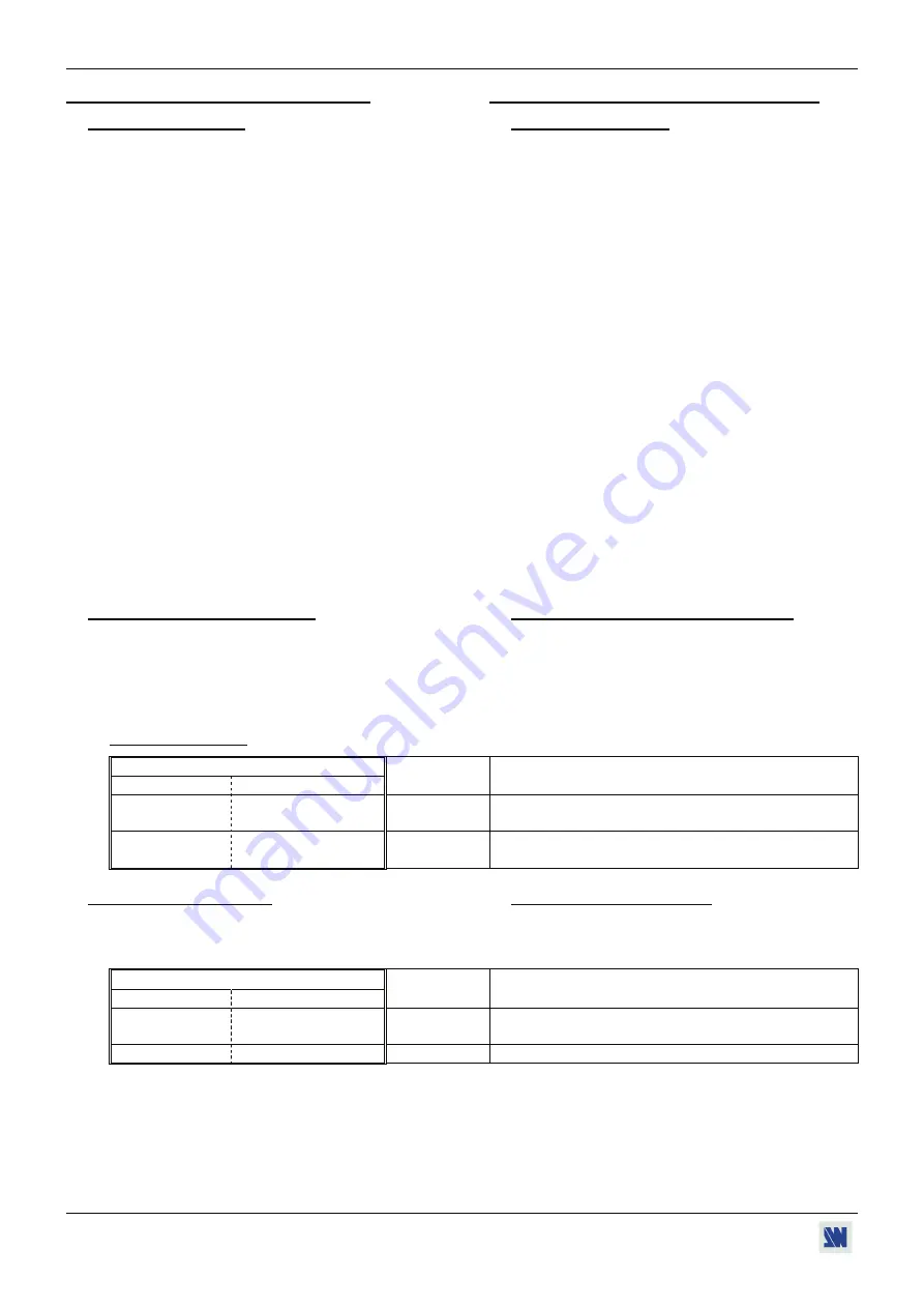
A-2: COMMANDS STRUCTURE 

Commands are usually composed of a numerical value 
followed by the command character. The characters used 
without any numerical value return the current setting of 
the command. 
Command = Value (optional) + Character. 

A-2: STRUCTURE D'UNE COMMANDE 

Les commandes sont généralement constituées d'une 
valeur numérique suivit par 1 ou 2 lettres de 
commande. Une lettre utilisée sans valeur numérique 
renvoie l'état de la commande. 
Commande = Valeur (optionnelle) + Caractère 

Examples / 

Exemples

Command / 

Commande


Value/ 

Valeur

 Character 

Caractère


Response 

Réponse 

Description 

none 


aucune


FY OSYN 

Read the output sync type. 

Lit le type de synchro. 

10 V 

VP10 

Set Vertical position to 10. 

Règle la position horizontale à 10. 


A-3: ERROR RESPONSES 

When the device receives from the control device an 
invalid command or value, it returns an error response: 

A-3: RÉPONSES D'ERREUR 

Lorsque l'appareil reçoit de l'appareil de contrôle une 
valeur ou une commande invalide, il retourne les 
messages d'erreur suivants:


Command / 

Commande


Value/ 

Valeur

 Character 

Caractère


Response 

Réponse 

Description 

none 


aucune


z E10 

Invalid command. / 

Commande invalide. 

70260 H 

E13 

Invalid value. / 

Valeur invalide. 

Summary of Contents for octo-fade 2 OFD803

Page 1: ...ANALOG WAY OCTO QFX402 EDITION 11 06 MODEL OFX803 MODEL OFD803 MODEL OCP803 MODEL QFX402 User s Manual...

Page 2: ...LAY DEVICE ADJUSTMENTS 21 3 4 IMAGE ADJUSTMENTS 21 3 5 AUDIO ADJUSTMENTS 21 Chapter 4 USING FRAME STORE AND LOGO INSERTION 22 4 1 LOGO INSERTION 22 4 2 USING THE FRAME STORE 23 Chapter 5 FRONT PANEL D...

Page 3: ...om wall outlet In both cases please follow these instructions The power cord of the device should be unplugged from the outlet when left unused for several days To unplug the device do not pull on the...

Page 4: ...s ouvertures Si un liquide ou un objet p n tre l int rieur de l appareil d branchez imm diatement l appareil et faites le contr ler par un personnel qualifi avant de le remettre en service ISTRUZIONI...

Page 5: ...idadosamente todas las consignas de seguridad y de funcionamiento del aparato antes de usarlo Conserve las instrucciones de seguridad y de funcionamiento para que pueda consultarlas posteriormente Res...

Page 6: ...ding d Select the fast or seamless switching mode with the LCD menu SWITCHING fast switching or seamless e Select the Auto settings function with the LCD menu INPUT Auto settings This function will de...

Page 7: ...eamless switching mode with the LCD menu SWITCHING fast switching or seamless e Select the Auto settings function with the LCD menu INPUT Auto settings This function will detect automatically the sour...

Page 8: ...16 million colors Recording is done either by direct acquisition from Input source or from Computer download of image files Up to 2 Logos can be assigned to each input to be displayed at any position...

Page 9: ...digital decoder improved 3 2 and 2 2 pull down circuitry auto adaptative pixel by pixel 3D motion compensation time base corrector frame rate converter follower Easy to use the device offers Auto Set...

Page 10: ...SET Selection of the CUT FADE TITLE effects OFX803 OFD803 FREEZE Freeze the output the blinking LED indicates the FREEZE is active LOGO OFX803 only Allows to display logo onto the output NOTE Logo dis...

Page 11: ...isplayed onto the output is indicate by a turn ON LED A long push 1 second on the selected input button allows to active the BLACK function A black screen is displayed onto the corresponding output A...

Page 12: ...HD15 and 2xBNC female connectors NOTE All the universal inputs accept the following video source Composite Video S Video SD YUV RGBHV RGBS RGsB HD YUV HDTV DISPLAY OUTPUTS DVI Digital analog output o...

Page 13: ...ctor 4 Universal computer and video input on HD15 and 2xBNC female connectors NOTE All the universal inputs accept the following video source Composite Video S Video SD YUV RGBHV RGBS RGsB HD YUV HDTV...

Page 14: ...panel switch Then turn ON all your input sources and then your display device Connection diagram 2 2 ANALOG WAY 4 1 2 3 3 2 2 QUATTRO FX CONNECTIONS NOTE Turn OFF all of your equipment before connect...

Page 15: ...gnment of this connectors Pin Function Pin Function Pin Function 1 TMDS Data 2 9 TMDS Data 1 17 TMDS Data 0 2 TMDS Data 2 10 TMDS Data 1 18 TMDS Data 0 3 TMDS Data 2 Shield 11 TMDS Data 1 Shield 19 TM...

Page 16: ...evice e AUDIO SOURCE You can connect an unbalanced stereo audio source on a jack 3 5 connector input 2 8 You can connect an unbalanced stereo audio source on a MCO connector input 3 to 6 You can conne...

Page 17: ...plug detect 24 TMDS Clock C1 Not used C2 Not used C3 Not used C4 Not used C5 Not used DDC Display Data Channel TMDS Transition Minimized Differential Signal 2 6 AUDIO INPUTS Each audio input has a 3 5...

Page 18: ...4 5 6 Unbalanced connection only Inputs 7 AUX Balanced unbalanced connection MCO male connector QFX402 The INPUTS 2 to 4 are equipped with this connector Connect your audio sources as follow Inputs 2...

Page 19: ...see the Switching mode table below e Select the Auto settings function with the LCD menu INPUT Auto settings This function will detect automatically the source type connected to the inputs of the dev...

Page 20: ...e reference computer input with the INPUT SELECTION button e Select another input The transition operates with a fading between the two sources TITLE The TITLE effect allows to insert text onto an ano...

Page 21: ...e with the LCD menu IMAGE Aspect ratio e Use the Centering function IMAGE Centering to automatically position the image in the Centering pattern IMPORTANT For best results display a full size bright i...

Page 22: ...o store another logos up to 8 HOW TO ASSIGN A LOGO NOTE You can assign the stored logos to one or many of the 8 inputs up to 2 logos by inputs g In the Assignment menu LOGOS FRAME Use logo Assignment...

Page 23: ...s d Select the Record frame mode LOGOS FRAME Record frame the device displays a white rectangle corresponding to the frame selection area onto the output If necessary adjust the position and size of t...

Page 24: ...enter in the CONTROL MODE In the CONTROL MODE press this button to return to the previous menu without safeguarding the selection return to the STATUS MODE press several times ENTER button From the S...

Page 25: ...3 3 Output rate 1 50 Hz 10 1600x1200 4 3 3 1280x720p 16 9 4 1024x768 4 3 5 1280x768 16 9 6 1366x768 16 9 2 Output format 1 852x480 16 9 2 800x600 4 3 7 VIS 8 Input 8 used 1 Auto setting 3 OUTPUT 1 Out...

Page 26: ...e 1 Auto follow 2 Input 1 9 Input 8 4 Audio level 5 Audio balance 6 AUX input OFF 7 AUDIO MAIN 1 Master volume 2 Audio mode 1 Mono 3s 5s effect duration xxs Custom Cut 6 Effect closing closing duratio...

Page 27: ...elect the input signal type with ENTER between SDTV Composite SDTV RGB SOG SDTV S VIDEO SDTV RGBS ana SDTV YUV Computer SOG SDTV RGBS TTL Computer HV C Computer DVI HDTV HDTV input format 720p 1035i a...

Page 28: ...60 Hz output frame rate 72 Hz 72 Hz output frame rate 75 Hz 75 Hz output frame rate 3 4 Output sync ENTER Select the Output Sync type with ENTER H V H V Separate Sync COMP Composite Sync SOG Sync On g...

Page 29: ...e entire image and the aspect ratio are preserved Crop The image is zoomed without deformation to fill the screen but some borders of the image will be cropped The aspect ratio is preserved Full Scree...

Page 30: ...puter 4 4 Aspect out ENTER Select one of the following output aspect ratio with ENTER Standard The entire image and the aspect ratio are preserved Crop The image is zoomed without deformation to fill...

Page 31: ...display ON or OFF a logo Adjust the duration with and validate with ENTER 5 2 Record logo ENTER This mode allows storing up to 8 logos in order to incrust them into the displayed image up to 2 logos a...

Page 32: ...Adjust the recording time with ENTER 5 3 8 Store ENTER This function allows storing the logo into the memory The memorization will take few seconds 5 4 Record frame ENTER This mode allows storing up t...

Page 33: ...the effect closing of the title between Cut Fade with ENTER 6 3 Key 3 Fading allows fading the pre selected input to the output You can select the duration of the transition as indicated below 1s 1 s...

Page 34: ...with ENTER From computer The CLEAN CUT operates only when switching from a computer source The others switching operates with a fade color From video The CLEAN CUT operates only when switching from a...

Page 35: ...number of host bits to be entered then calculates the netmask which displays in standard decimal dot notation when the saved parameters are displayed Select the netmask with ENTER Default value 255 25...

Page 36: ...lect YES and validate with ENTER 8 9 Default value ENTER This function allows setting the following functions to the factory settings Select YES and validate with ENTER FUNCTION POSITION input type Co...

Page 37: ...allation Then with the front panel display menu configure the LAN communication port CONTROL LAN setup and activate the LAN communication port CONTROL RS232 LAN port LAN 6 2 UPDATE INSTRUCTIONS c Swit...

Page 38: ...Select the language of the CD ROM menus then click on Install a Remote Control Software and select the name of your device IMPORTANT If the Autorun is not enabled From the Windows desktop open My Comp...

Page 39: ...2 LAN port LAN With the Controls menu of the software select RS232 LAN setup and LAN Setup Then configure the Local port the Remote IP address and the Remote port and click on Apply to setup the new v...

Page 40: ...he Switching mode internal rate input rate or seamless then selects the needed adjustment output sync output format output rate e Click on the Image tab and adjust your input f Click on the Audio tab...

Page 41: ...0 x 1200 60Hz RB reduced blanking and 1920x1080 60Hz RGB S VIDEO Connectors HD15 inputs 2 to 8 and DVI I input 1 Frequency 15 625 kHz 50 Hz 625 lines 15 734 kHz 60 Hz 525 lines Levels R G B 0 7 Vp p S...

Page 42: ...UTPUTS ANALOG Connectors HD15 and DVI I 2 x buffered Resolution 4 3 5 4 800x600 1024x768 1280x1024 1400x1050 1600x1200 16 9 16 10 852x480 1280x720 1280x768 1366x768 1920x1080 Frame frequency 50 60 72...

Page 43: ...r Jack 3 5 mm female Command levels ON 12 Vdc trigger OFF 0 Vdc Output Current 0 1 A max at 12 Vdc NOTE This output is activate with the AC Power Switch ON OFF 8 7 ENVIRONMENTAL Power Supply Internal...

Page 44: ...n est pas n cessaire d appuyer sur ENTER du clavier Une commande peut tre pr c d e d une valeur voir chapitre A 2 Lorsque l appareil re oit une commande valide il ex cute cette commande puis renvoie l...

Page 45: ...PR RGB input type selection works with PC command Rd Wr 0 10 0 composite 1 S VIDEO 2 YUV 3 RGBS TTL 4 RGsB SOG 5 RGBS ana 6 computer SOG 7 comp HV or C 8 computer DVI 9 HDTV YUV 10 audio only PI PI In...

Page 46: ...10 200 10 10 100 100 no zoom 200 200 ZH ZH Zoom horizontal position Rd Wr 0 255 ZV ZV Zoom vertical position Rd Wr 0 255 QR QR Red level adjustment Rd Wr 0 255 QG QG Green level adjustment Rd Wr 0 25...

Page 47: ...Lu Vert position of the logo storing area Rd Wr 0 255 LK LK Horizontal size of the logo storing area Rd Wr 5 255 5 3 255 100 Lk Lk Vertical size of the logo storing area Rd Wr 5 255 5 3 255 100 LQ LQ...

Page 48: ...size of the logo storing area with the LU Lu LK and Lk commands e Select the Luma key type Le command adjust the luma key level LE command and the background color with Lb command f Select a logo mem...

Page 49: ...1 Default value action automatic reset COMMUNICATION COMMANDS COMMANDES DE COMMUNICATION ne ne Communication port selection Rd Wr 0 1 0 RS232 1 LAN nr nr Reset of the LAN parameters Rd Wr 0 1 1 reset...

Page 50: ...on Rd 0 1 0 In range 1 Out of range IF IF Standard input signal detection Rd 0 35 0 no signal 1 wrong signal 2 NTSC std 3 58 60 3 PAL std 4 43 50 4 SECAM 50Hz 5 B W 50Hz 6 B W 60Hz 7 YUV 50Hz 8 YUV 60...

Page 51: ...9 41 I 49 73 i 69 105 2A 42 J 4A 74 j 6A 106 2B 43 K 4B 75 k 6B 107 2C 44 L 4C 76 l 6C 108 2D 45 M 4D 77 m 6D 109 2E 46 N 4E 78 n 6E 110 2 F 47 O 4 F 79 o 6 F 111 0 30 48 P 50 80 p 70 112 1 31 49 Q 51...

Page 52: ...uding free materials and labor This warranty does not apply if the product has been improperly installed or abused handled with improper care used or stocked in abnormal conditions modified opened dam...

Reviews: