ADV8005 Hardware Reference Manual
UG-707
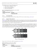
Figure 52
Auto-Position Software Flow Chart
auto_phpo_inp_sel[1:0]
, IO Map,
Address 0x1BE0[7:6]
This control signal is used to select which input is routed to the auto position and auto phase blocks
Function
auto_phpo_inp_sel[1:0]
Description
00 (default)
VID TTL
01
OSD TTL
10
RX
11
N/A
auto_phpo_byp_csc
, IO Map,
Address 0x1BE0[5]
This bit is used to bypass the CSC or not before routing to the auto Phase and auto Position detection blocks
Function
auto_phpo_byp_csc
Description
0
CSC output used for auto PHPO
1 (default)
CSC input used for auto PHPO
Set front end pll ratio
first,
then enable manual pll
Increase fend horizontal
blanking area
Set fend datapath and
AVI to RGB
Ignore blanking area
Set ADV8005 datapath
to RGB (no CSC)
Initialize
noise threshold (0x80)
Enable auto position
IO Map, 1BE7[7]
Read measurement
Increase noise
threshold
Reset auto position
Lock?
Time
out?
Adjust front end
sampling clock
frequency
yes
no
no
yes
ADV7850
VFE map - 0x16,0x17
ADV7850
CP map -0x8C,0x8D
IO 0x1B49[5],0x1B89[7]
Front End write
ADV8005 write
Detect video standard
Correct
timing?
yes
END
no
Reset auto position
ADV7850
VFE map -0x16,0x17
IO map - 0x1BE0[7:6]
IO map - 0x1BE7[1:0], 0x1BE8[7:0]
IO map - 0x1BEA to 0x1BF1
IO map - 0x1BFE[0]
Based on video
standard detected
IO map - 0x1BE0[5]
IO map - 0x1BE9[1:0]
IO map - 0x1BFE[0]
Select TTL/RX input
Rev. A | Page 101 of 317


