


EVAL-ADP5520
Rev. 0 | Page 9 of 24
AUX LEDS CONFIG TAB
07
65
1-
0
05
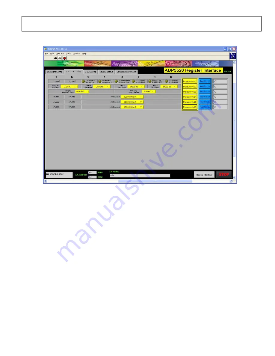
Figure 5. Aux LEDs Config Tab
AUXILIARY LED TURN-ON/TURN-OFF
First press the reset button (S17) on the evaluation board to put
the device in a known state; then complete the following steps.
1.
On the motherboard, do the following:
a.
Move the jumper on Block J8 to the LED 2 position.
b.
Move the jumper on Block J4 to the LED 3 position.
2.
On the
Aux LEDs Config
tab, do the following:
a.
In the
LED 1 Current
drop-down box, select the
LED 1 sink current setting (for example, 14 mA); then
program this setting by clicking the
Program 0x14
button.
b.
In the
LED 2 Current
drop-down box, select the
LED 2 sink current setting (for example, 14 mA);
then program this setting by clicking the
Program
0x15
button.
c.
In the
LED 3 Current
drop-down box, select the
LED 3 sink current setting (for example, 14 mA);
then program this setting by clicking the
Program
0x16
button.
d.
Set Bit 0, Bit 1, and Bit 2 in Register 0x11 high; then
program these settings by clicking the
Program 0x11
button.
3.
On the
BackLight Config
tab, set Bit 7 in Register 0x00
high; then program this setting by clicking the
Program
0x00
button.
All three auxiliary LEDs turn on.
4.
To turn off an LED, clear Bit 0, Bit 1, and/or Bit 2 in
Register 0x11 on the
Aux LEDs Config
tab.
You can modify the sink current in each LED by changing the
settings in Register 0x14, Register 0x15, and Register 0x16.
AUXILIARY LED TURN-ON/TURN-OFF WITH FADE-
IN/FADE-OUT
First press the reset button (S17) on the evaluation board to put
the device in a known state; then complete the following steps.
1.
On the motherboard, do the following:
a.
Move the jumper on Block J8 to the LED 2 position.
b.
Move the jumper on Block J4 to the LED 3 position.
2.
On the
BackLight Config
tab, set Bit 7 in Register 0x00
high; then program this setting by clicking the
Program
0x00
button.
3.
On the
Aux LEDs Config
tab, do the following:
a.
In the
LED 1 Current
drop-down box, select the LED 1
sink current setting (for example, 14 mA); then pro-
gram this setting by clicking the
Program 0x14
button.
b.
In the
LED 2 Current
drop-down box, select the LED 2
sink current setting (for example, 14 mA); then pro-
gram this setting by clicking the
Program 0x15
button.


