background image


28 


Important! 

In the case where the modules are retracted and inspection on cables is difficult, use the Second special boot-up 
mode to move actuators manually. Refer to section 3, E-bx special boot-up modes and position reset. The section 
below 

describes methods on “How to” and provides “additional information”.


4.1.5.1


How to and additional information 

4.1.5.1.1


Checking battery voltage 


Examples of batteries with a low voltage 

There are two methods to check battery voltage: 

1.


Visually, on the joystick

’s battery voltage level display


Refer to example above

If only one light is on or flashing, the battery voltage is less than 23.5 Volts. When battery voltage falls 
below that, the e-bx and the R-Net power module can generate error codes. A fully charged battery will 
have all 10 lights on. The voltage should be between 25.3 and 27.5 Volts. 

2.


Using a multimeter in voltage mode, connect probes directly to the joystick’s charger port positive 

and 

negative terminals. 

Refer to the images below showing probe connections from multimeter to joystick

Turn on multimeter and set it to “V” for voltage

 mode. Select DC voltage reading mode. It is not possible 

to get a proper voltage reading in AC mode. Probes must be well connected to desired terminals to obtain 
a reliable reading. 
 

CAUTION

! Extreme care must be taken while connections are made between multimeter probes and 

desired terminals when reading current measurements because there is a risk of damaging multimeter, 
probes and chair; of burning oneself; of getting pieces of metal in the eye when getting a reading. 

Summary of Contents for E-BX

Page 1: ...1 E BX IG P17008 Instruction Guide E BX R01...

Page 2: ...9 2 1 5 1 Settings under the Axis Setup submenu 9 2 1 5 2 Approximate length of time for actuator deployment 10 3 E bx special boot up modes and position reset 10 3 1 Overview of both special boot up...

Page 3: ...ing battery voltage 28 4 1 5 1 2 Verifying power cables 29 4 1 5 1 3 Verifying R Net bus cables actuator cables and intermittent problems 33 5 Replacing pushbuttons in keypad SWKEYPAD 35 5 1 Pushbutto...

Page 4: ...olled by e bx use the following path Seating Amylior ISM Actuator Setup In this submenu the legend for each actuator number is as follows 1 Seat tilt actuator 4 Center mount legrest actuator 2 Backres...

Page 5: ...ting for seat elevate position Fully elevated percentage of range Note 3 0 to 100 100 Min limit 4 or Actuator 4 Center mount Minimum setting of center mount legrest position Legrest fully elevated min...

Page 6: ...ded is 5 5 inches 5 5 X100 11 50 Therefore the height limit value of Max limit 3 is 50 Note 4 Not applicable on actuators for heavy duty seat elevate 300 lb to 400 lb Note 5 If the chair has the power...

Page 7: ...r 60 Set point 11 Not used Settings for future development Set point 12 Acceleration For all actuators except the stander actuator The standing module follows a specific pattern when deployed and do n...

Page 8: ...egrests 8 Center mount legrest 9 Recline and Center mount legrest 10 Not used 11 Memory positions 1 2 12 Memory positions 3 4 For chairs with the power standing option the following table shows basic...

Page 9: ...uators for the standing function 25 to 100 Note 1 Down Speed Standing function only Percentage value of retraction speed of actuators for the standing function Control All functions assigned to an axi...

Page 10: ...the setting to proportional This can affect the standing function s performance and create errors while in motion Before modifying this setting contact Amylior for approval Note 3 For both axes reserv...

Page 11: ...roblem with the controller This mode can also be used for an actuator position reset In this mode all movement limitations will be disabled except for minimum and maximum limits for each actuators und...

Page 12: ...ed a position reset of actuators can be done by moving the targeted actuators from the minimum position to the maximum position using the keypad SWKEYPAD Retract all actuators to neutral position befo...

Page 13: ...SWKEYPAD that correspond to the stander actuators Move stander actuators to a full deployment both upper buttons followed by a complete retraction both lower buttons IMPORTANT When an actuator is rep...

Page 14: ...ndicator light underneath the e bx flashes If there is an error the green indicator light underneath the e bx can indicate certain error codes The error is shown with a two second pause separating the...

Page 15: ...port Remove the chair s backrest cover Plug the R Net dongle into the chair by removing one of the R Net cables connected to the chair for example one of the 2 cables connected to the e bx and turn on...

Page 16: ...16 Click on the Tools tab Click on Systems Logs menu The following window will appear on the left Click on the Log tab and select Read menu...

Page 17: ...the Dealer version of the application The file containing the error codes must be sent to Amylior to be examined and analyzed To save the journal of error codes click on the File tab and select Save t...

Page 18: ...and turn it back on 2 If the problem persists replace the e bx 9601 14 9602 14 9603 14 9604 14 9605 14 9606 14 9607 14 9608 14 Wrong version of R Net 1 If necessary update the e bx firmware 2 If the...

Page 19: ...mponents as required 9643 9644 3 The actual voltage of the 12 volt supply in the e bx s internal circuitry is too low 1 Reset alarm by turning chair off and back on making sure the error does not reoc...

Page 20: ...a multimeter is not available and nothing is inconsistent or damaged reconnect each actuator extension cables one by one to the e bx until an error pops up and verify which cable or which actuator cau...

Page 21: ...if one or more actuators constantly stop during movement under a load e g with user in chair 5 Replace the actuator s that appear s to constantly stop under a load 6 If none of the actuators constantl...

Page 22: ...perform a Return to factory settings while referencing the PGDT SK78009 manual 965B Both speed and power option indicator lights turn off The level on the battery voltage turns off then one light flas...

Page 23: ...he problem persists replace the e bx 9661 Battery voltage level indicator light flashes twice and power options indicator light turns off 6 The tilt actuator is defective or actuator ID card is faulty...

Page 24: ...or left stander actuator 5 connected to the same e bx 9666 6 The right legrest or right stander actuator is defective or actuator ID card is faulty More than one right legrest or right stander actuat...

Page 25: ...r supply is getting to the e bx and the connection between the R Net bus cable and the e bx is good replace the e bx 4 If the 24 V power supply is not reaching the e bx verify that the R Net bus cable...

Page 26: ...If error 9663 did not appear after a complete seat elevate position reset turn chair off and back on 4 Try moving seat elevate again If errors do not appear the problem was that the actuator had lost...

Page 27: ...witch points down b A reading below 0 9 Ohms is needed when the head of the tip limit switch points up c Repeat these 2 previous steps several times in order the get a reliable reading If this result...

Page 28: ...e bx and the R Net power module can generate error codes A fully charged battery will have all 10 lights on The voltage should be between 25 3 and 27 5 Volts 2 Using a multimeter in voltage mode conne...

Page 29: ...rdigris near the terminals Open the battery compartment and remove the two 12 Volt batteries Disconnect both batteries from the chair by pulling on the black Anderson connector to separate both parts...

Page 30: ...er To avoid false readings be sure to properly connect probes to desired jacks for a reliable resistance reading Connect the end of the probes together and wait for the reading on the multimeter to st...

Page 31: ...e measured between the circuit breaker terminals should not exceed 0 1 Ohms If the result of the resistance reading of the circuit breaker shows a value of O L Infinity reset by pressing the black but...

Page 32: ...c scouring pad Do not use steel wool Once the contacts are clean reconnect the fuse and secure bolts so that the fuse terminals cannot move at all Check for continuity again Replace the fuse if in dou...

Page 33: ...33 4 1 5 1 3 Verifying R Net bus cables actuator cables and intermittent problems Verify that all cables are properly connected and well secured as shown below R Net bus cable connection...

Page 34: ...d replacing it with a temporary cable that does not belong to the chair By using a temporary external cable time will be saved since it will be possible to determine which cable is truly faulty withou...

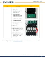
Page 35: ...URE TO HAVE ALL THE REQUIRED MATERIALS Tools and material 1 Screwdrivers Phillips 1 and 2 2 Allen key 2 5 mm 3 Replacement pushbuttons 4 Cutters 5 Tie wraps 2 REPLACING PUSHBUTTONS 1 Cut ties securing...

Page 36: ...k and secure the 8 screws Do not over tighten 11 Close cover 12 Secure the 4 screws on cover 13 Reinstall keypad on its mount and secure the 2 screws using 2 5 mm Allen key 14 Connect keypad to chair...

Reviews: