Installation Guide
ViewStat Communicating Thermostat (VST)
ATTENTION: READ THIS FIRST!
Additional Documentation
For additional installation, configuration, programming and operating instruction, refer
to the
ViewStat Communicating Thermostat Instruction Manual
and
ViewStat Protocol
Reference Guide
documents, available on-line, at
www.amx.com
.
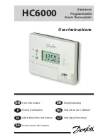
The ViewStat Communicating Thermostat (FIG. 1) operates similarly to a conventional
thermostat but has the unique capability of being controlled, either locally or remotely
from a NetLinx or Landmark control system. The ViewStat is compatible with any
24-volt controlled HVAC system. This manual describes how the ViewStat connects to
several different types. See the
ViewStat Communicating Thermostat Instruction
Manual
(available online at www.amx.com) for details.
If necessary, contact AMX Technical Support for help with additional specific control
wiring scenarios
.
The ViewStat is designed to work with VST-TTM (Temperature) and VST-TRH
(Temperature and Humidity) support modules, and remote sensors.
Connecting the ViewStat to AMX Control Systems
The Viewstat (VST) has a single RJ-45 jack on the rear panel, and uses ICSNet
cabling to connect to NetLinx or Landmark control systems.
Note
: The terms "PhastLink" and ICSNet" are essentially interchangeable within the
context of cabling/connectors. They both use a standard 10BaseT type connection
(i.e. Category 5 wire and RJ-45 connectors), and they share the same pinout
information for the RJ-45 jacks. Generally the term "PhastLink" is used when dealing
with Landmark, and "ICSNet" is used when describing NetLinx control systems.
PHASTLink cables follow the EIA/TIA 568
A
color code, and NetLinx cables follow the
EIA/TIA 568
B
color code. The wires should be connected in the standard manner
described in the following table.
If standard EIA/TIA 568A/B color coding is followed, wiring problems will be minimized.
Note: It is important that the correct pairing is observed.
Transmit, Receive, and
Mic need to be on twisted pairs. Splitting pairs (e.g., using a white/green wire with a
blue/white wire for transmit) will result in increased crosstalk, and may result in bus
failure or noise on the intercom.
Installing the Cat5 Suppression Ferrite
Before connecting the ICSNet cable, install the CAT5 Suppression Ferrite (provided),
as described below (no tools required):
Connecting to a NetLinx Control System
To connect a single VST to a NetLinx control system
, use ICSNet cabling to connect
the RJ-45 jack on the VST to any available ICSNet jack on the NetLinx Master. The
maximum cabling distance between the VST and Master is 1,000 ft. (304.8 m).
To connect multiple ViewStats to a NetLinx system
, use a NetLinx Hub (NXC-NH) to
add additional ICSNet ports to the system. Connect the RJ-45 jack on the VST to an
available ICSNet jack.
Connecting to a Landmark Control System
To connect a single VST to a Landmark control system
, use PhastLink cabling to
connect the RJ-45 jack on the VST to any available PhastLink jack on the Landmark
Master. The maximum cabling distance between the VST and Controller is 1,000 ft.
(304.8 m).
To connect multiple ViewStats to a Landmark system
, use a Landmark Hub (PLH-
RPT) to add additional PhastLink ports to the system. Connect the RJ-45 jack on the
VST to an available PhastLink jack.
Connecting the ViewStat to the HVAC System
Before connecting the VST to the HVAC system, install the 24 VAC Suppression
Ferrite, to eliminate any potential noise problems.
Installing the 24 VAC Suppression Ferrite
Before connecting the 24 VAC power supply cable to the HVAC system, install the 24
VAC Suppression Ferrite (provided), as described below (no tools required - see
FIG. 3).
Setting the DIP Switch
Set the DIP switch located on the thermostat circuit board (FIG. 4) according to the
application needs (see the
DIP Switch Settings table
below for details).
FIG. 1
ViewStat Communicating Thermostat
PHASTLink RJ-45 Pinout Information (EIA/TIA 568 A)
Pin
Wire Color
Polarity
Function
1
White/Green
+
Transmit
2
Green
-
Transmit
3
White/Orange
-
Mic
4
Blue
-
Ground
5
White/Blue
+
12 VDC
6
Orange
+
Mic
7
White/Brown
+
Receive
8
Brown
-
Receive
hinged
base
Communication
HVAC Equipment
terminals
terminals
front panel
Message display
Main display
Scroll/Setup
Adjust buttons
buttons
Fan button
Enter button
Mode
button
TIA 568A
NetLinx RJ-45 Pinout Information (EIA/TIA 568 B)
Pin
Wire Color
Polarity
Function
1
Orange/White
+
Transmit
2
Orange
-
Transmit
3
Green/White
-
Mic
4
Blue
-
Ground
5
White/Blue
+
12 VDC
6
Green
+
Mic
7
White/Brown
+
Receive
8
Brown
-
Receive
FIG. 2
Installing the CAT5 Suppression Ferrite
TIA 568B
1 2 3 4 5 6 7 8
1
2
3
4
5
6
7
8
RJ-45 connector - pin configurations
(female)
(male)
1. Release the latch to open
the plastic enclosure.
2. Insert the Cat5 cable
and close the enclosure.
3. Installation
complete.


