

QUICK START GUIDE
SDX-810-DX
Solecis
®
Digital Switcher
Overview
This guide pertains to the SDX-810-DX 8x1 HDMI Digital Switcher with DXLink Output
(
FG1010-308
). The purpose of this document is to illustrate how the device is to be
installed and set up in its simplest configuration by a trained technician.
Additional Documentation
Additional documentation for this device is available at www.amx.com. Refer to the
Solecis SDX Digital Switchers Instruction Manual
for additional details on installing,
upgrading, and wiring the SDX-810-DX.
You can also access this Quick Start Guide online by using your mobile device to scan
the QR code located on the bottom of the SDX-810-DX.
What’s in the Box?
The following items are included with the SDX-810-DX:
• (2) rack ear brackets
• (4) #8-32 x .375 screws
• (4) #10-32 x .625 screws
• (4) #10 black nylon washers
• (4) 5-pin Phoenix connectors
• (1) 4-pin Phoenix connector
• (4) rubber feet
Power
Active power requirements:
• Voltage, DC (typical): 12VDC
• Power consumption (max): 21W
Environmental Requirements
The environmental requirements for the SDX-810-DX are as follows:
•
Operating Temperature
: 32° F (0° C) to 104° F (40° C)
•
Storage Temperature
: -22° F (-30° C) to 158° F (70° C)
•
Operating Humidity
: 5% to 85% RH (non-condensing)
•
Storage Humidity
: 0% to 90% RH (non-condensing)
Configuration
Perform the following to prepare the switcher for network communication:
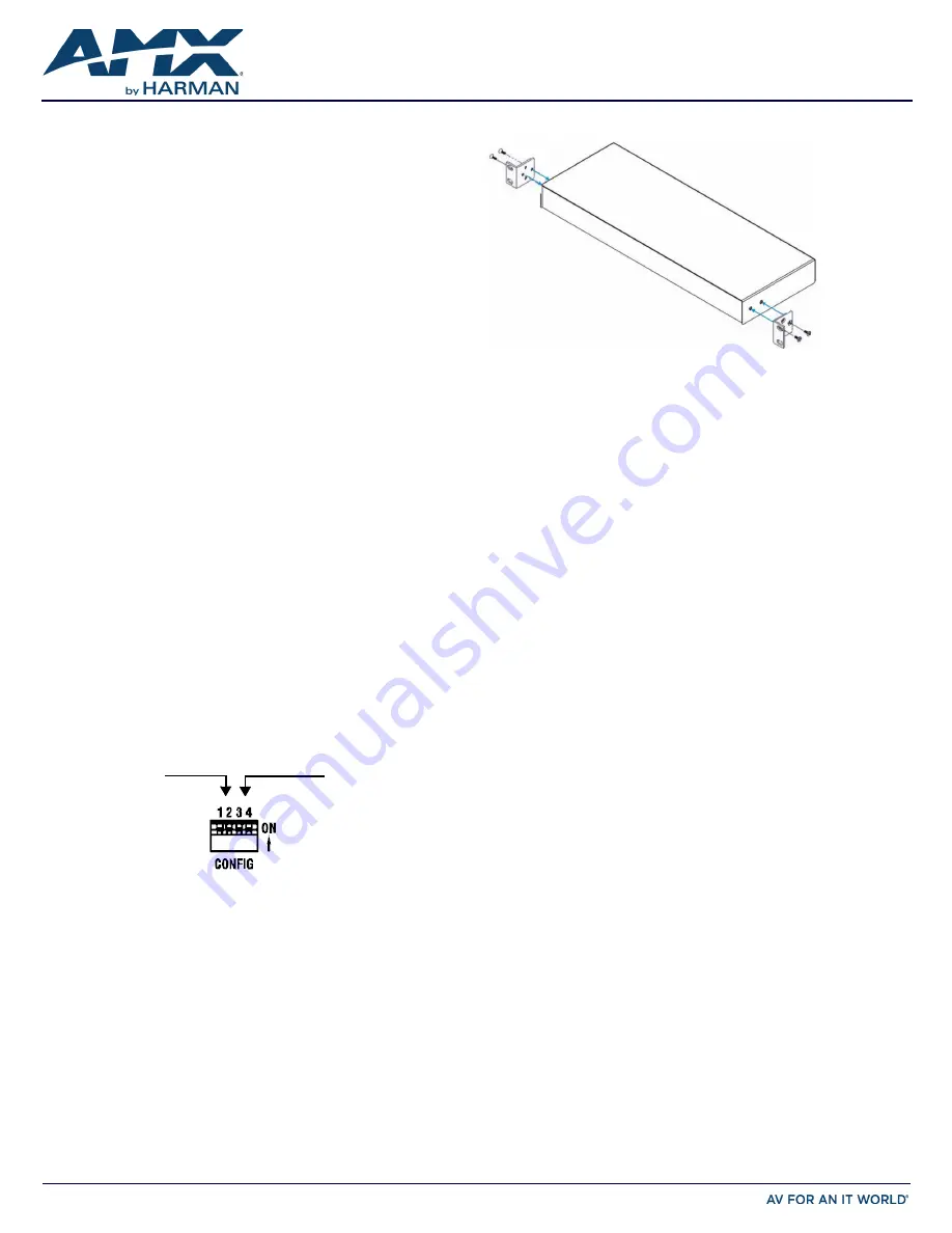
Setting the Configuration DIP Switches
Use the Configuration DIP switch to enable/disable the LAN ports and set network
connectivity. DIP switch settings are read on reboot. Any changes to the DIP switch
settings are not acted upon until after you reboot the device.
Enabling the LAN 10/100 Ports
The LAN 10/100 ports on the switchers are disabled by default. You can enable the
ports by setting #1 DIP switch to ON (see FIG. 1).
Enabling Network Connectivity
Network connectivity on the switchers is disabled by default. You can enable network
connectivity by setting #3 DIP switch to ON (see FIG. 1).
FIG. 1
CONFIGURATION DIP SWITCH
Installation
Before connecting the switcher to its peripheral devices and powering the device, be
sure to mount the device using one of the methods detailed below. You can also pole-
mounted the switcher using the V Style Single Module Pole Mounting Kit (
FG1010-723
).
The switchers also include rubber feet that you can apply to the bottom of the device
for table-top mounting.
Surface Mounting
The Solecis Digital Switchers can be mounted using the rack ear brackets included with
the switcher. The rack ear brackets are designed for mounting a single module (to a
wall, on or under a desk, etc.) The included brackets can be rotated 90° in any direction
to accommodate several different mounting options, including rack mounting, tabletop,
under/over the table, and vertical wall mounting.
Position and install the mounting brackets, as shown in FIG. 2, using the supplied
washers and mounting screws.
FIG. 2
MOUNTING THE RACK EARS ON THE SDX-810-DX
Getting Connected
The following sections describe how to connect your switcher to your network, audio/
video sources, and accessories.
Connecting the Switcher to a Video Input
The HDMI INPUT connectors on the rear panel route digital video (and audio) from
connected source input devices to the connected output devices. The SDX-810-DX
features eight HDMI INPUT connectors.
Connecting the Switcher to a Video Output
The switchers can transmit a signal simultaneously to both DXLink and HDMI outputs.
• The switcher uses standard HDMI cabling to connect to the HDMI inputs and
outputs. Use an HDMI cable to connect the HDMI OUT port on the rear panel of
the switcher to the display device.
• The switcher uses category cabling to connect to the DXLink output. See the
Important Twisted Pair Cabling Requirements and Recommendations
section for
information about cable requirements for the DXLink port. Use category cabling
to connect the DXLINK port on the rear panel of the switcher to the DXLink input
port on a DXLink receiver, Enova DVX switcher, or Enova DGX switcher.
Video Switching
Auto Switching mode is the default switching mode. With Auto Switching mode, the
switcher responds to the most recently added video input by switching the new input to
display on the HDMI and DXLink output. If the currently selected video source is
removed, the switcher remains on that input.
You can disable Auto Switching mode by using the VIDIN_AUTO_SELECT NetLinx
command. See the
Solecis SDX Digital Switchers Instruction Manual
for more
information on this command.
To switch between video inputs that have already been established, you can perform
one of the following:
• Use the Select button on the front of the panel to cycle through the video inputs.
• Use a connected external button (not included) with any of the four External
Button/LED Control connectors located on the rear panel of the switcher. The
External Button/LED Control connectors are 5-pin, 3.5mm terminal screw
connectors to which you can connect up to two single-button modules, such as
the HPX-U100-BTN. With a single button module connected to one of these ports,
you can press the button on the module to switch the input and send a button
press event to a connected Master. You can use this function to have the Master
send a command back to the switcher to execute an additional event.
• Use the NetLinx command CI<input>O<output> to switch between video inputs.
See the
Solecis SDX Digital Switchers Instruction Manual
for more information on
this command.
Toggling Between DHCP and Static IP Addresses
Solecis Digital Switchers support both DHCP and static IP addresses. When the #3 DIP
switch is set to ON, the switchers automatically use DHCP with link-local fallback.
However, you can use a static IP address which you can set via a Telnet command (SET
IP), or you can use the factory default static IP address. The default static IP address
can be recalled at any time by resetting the unit to its factory default configuration. The
default link-local address is 169.254.2.2. The switcher defaults to the link-local address
if no IP address is obtained from a DHCP server.
The ID Pushbutton can be used to toggle between the DHCP and Static IP Modes.
Perform these steps to toggle between IP addressing modes:
1.
After the switcher boots, press and hold the ID Pushbutton until the STATUS and
LINK/ACT LEDs toggle back and forth in unison approximately 10 times.
2.
Release the pushbutton when the LEDs start to blink faster.
• When you release the Pushbutton, the switcher toggles either from static to
dynamic (DHCP) IP addressing or vice versa and remains in that mode until you
use the ID Pushbutton to toggle the IP mode again or you perform a factory reset.
• The switcher automatically reboots to complete the process.
#1 switch, set to ON
to enable
LAN 10/100 ports
#3 switch, set to ON
to enable network
connectivity


