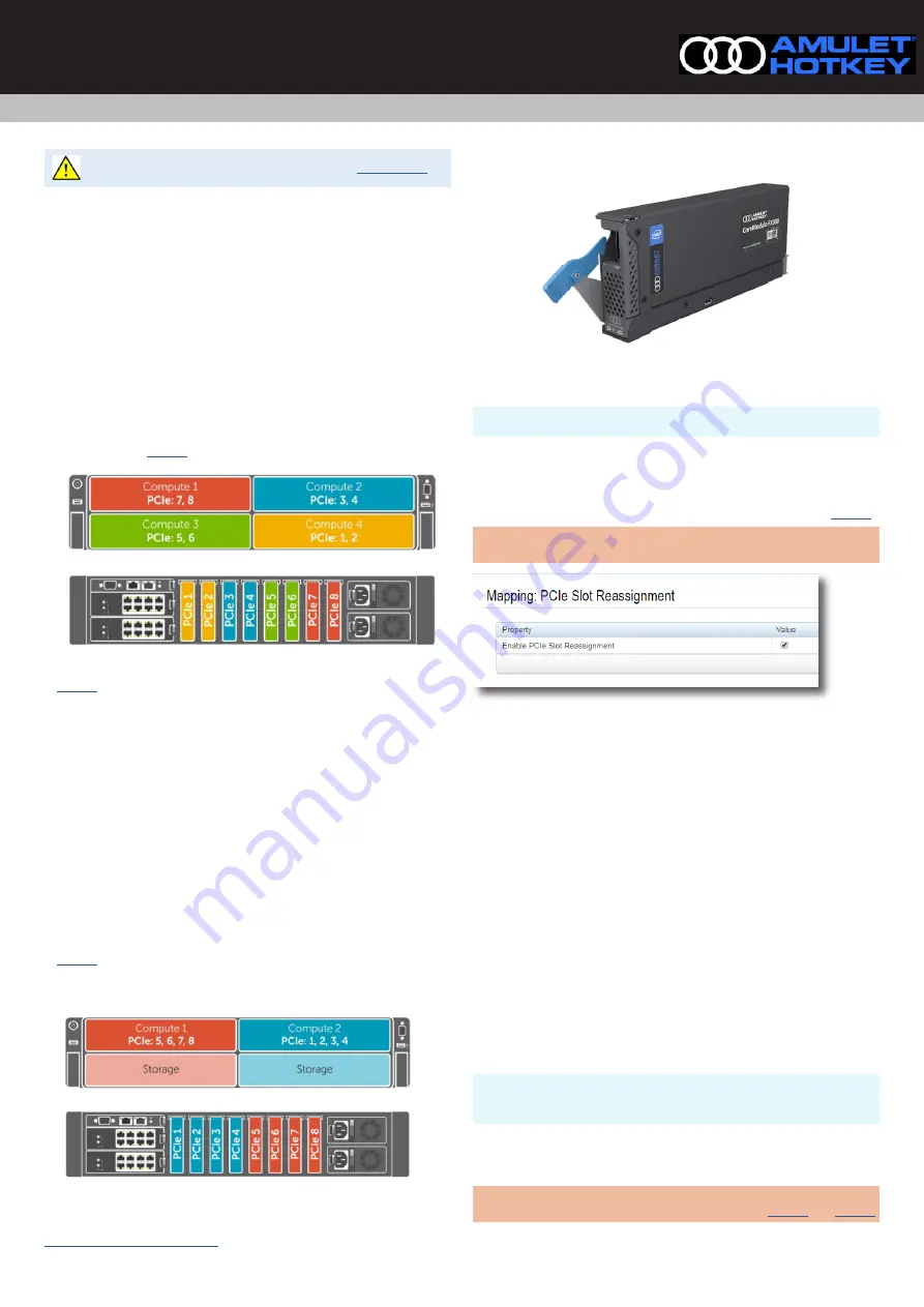
FX2s CoreModule™ FX300 (Single-Width Taco)
Remote Workstation solutions for Dell FX2s FC630/FC640 blade servers
Quick Start Guide
QS-FX30-0001 v1.0 February 2021
For Health and safety information, refer to the sheet
The Amulet Hotkey® CoreModule™ FX300 is a unique, single slot PCIe expansion
module for the Dell PowerEdge FX2 chassis. incorporating a
Each CoreModule FX300 contains one Intel® Programmable Acceleration Card
(PAC) with the Intel® Arria® 10 GX FPGA. The Aria 10 provides data centers
with both inline and lookaside acceleration, high-performance and outstanding
versatility. The FX300 delivers superior scalability, reliability and performance.
There may be different ways to configure, depending on use case. As well as
explaining the basic installation of the FX300, this guide gives setup examples of
how to use an CoreModule FX300 with an FC640 for remote access to the FGPA.
Assign two module slots to one blade (default)
Each CoreModule FX300 contains one Aria PCIe card that maps to a blade
installed in the top/bottom position in the same side at the front of the FX2s
chassis as shown in
Figure 1:
Four blade configuration example
In
the CoreModule FX300s in positions PCIe1 & PCIe2 at the rear left
hand side (LHS) connect with a blade in the bottom Compute 4 position on the
right hand side (RHS) at the front.
The second pair (PCIe3 & PCIe4) connect to the blade in the top Compute 2
position on the same side.
The third pair (PCIe5 & PCIe6) connect to the bottom Compute 3 position on the
front LHS.
The fourth pair (PCIe7 & PCIe8) connect to Compute 1 in the top position on the
front LHS.
Assign four module slots to one blade
If only one blade is used on half of the chassis, the space below can be empty,
contain a storage sled, or a compute sled with no PCIe expansion requirement.
In
, four CoreModule FX300s connect with a single blade in the top
Compute position. So Compute 1 connects to PCIe5, 6, 7 & 8 on the RHS (rear).
Compute 2 connects to PCIe 1, 2, 3, 4 on the LHS (rear).
Figure 2:
Two blade configuration example
How to select the mapping for four module slots to one blade
Caution:
!
This is only possible when all sleds or blades are powered down.
1
Login to the CMC with the IP address, username and password.
2
Select PCIe Overview from the left-hand menu and click the Setup tab.
3
Make sure the Enable PCIe Slot Reassignment box is checked. See
.
Note:
This selection is automatic when a storage sled is installed in the chassis
slots Compute 3 or Compute 4, reassigning the slot below to the slot above.
Figure 3:
Reconfigure the iDRAC for alternative slot reassignment
Prepare the blades in the FX2s chassis
1
For a new install, power down all the blades.
2
For an existing configuration (if applicable):
a). shut down or migrate all VMs hosted by the blades;
b). in the VMware vSphere client, locate the ESXi server in the Inventory and
put it in to Maintenance Mode;
c). power down any blades that will connect to the CoreModule FX300.
3
Remove any PCIe modules that occupy the slots where you will install the
CoreModule FX300.
Install a CoreModule FX300 module in a PCIe slot
The CoreModule FX300 module installs easily into the rear of the FX2s chassis
into one of the eight slots of the expansion bay.
Do the following steps to install each module.
Caution:
!
Always use anti-static handling procedures, such as wearing a
wrist-strap, before handling the CoreModule FX300.
1
Remove all packaging and the connector protector from the module.
2
Decide which is the correct position to install the module(s).
Note:
Make sure you install the CoreModule FX300 module in the correct PCIe
slot of the expansion bay for your configuration. Refer to


