AM-TC10626LA
7
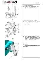
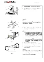
Fig 5-a
Fig.5-b
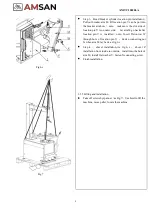
Fig.5-c
3.3.
Installation
3.3.1
Column installation
⚫
Screw off connecting bolts A and flat washer
B. As Fig.5-a
⚫
As fig. 5-b, put column C on the frame
F, locked into mounting holes with D10X55
hexagonal bolts and flat washer E
,
fasten with
connecting screws.
NOTE
:
When
column
installation,
keep
column vertical, prevent it from tilting, avoid
injury!
3.3.2
Vertical column installation
⚫
Install vertical column G into column hole on
the swing arm H from downside to upside,
lock vertical column with lock lever L.
(
note
:
Care
about
mounting
head
installation
direction. Place a rim on t h e
turntable for reference
;
then install return
spring I, knob J, fasten connecting screw K. as
fig. 5-c
NOTE
:
When screwing off
K, please lock
vertical column G with lock lever L as
column G will fall automatically, take care!
Summary of Contents for AM-TC10626LA
Page 1: ...PLEASE READ THE PRODUCT MANUAL ENTIRELY BEFORE INSTALLING OR OPERATING THE LIFT ...
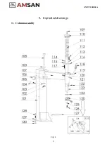
Page 22: ...Fig 34 21 AM TC10626LA 9 1 Column assembly 9 Exploded drawings ...
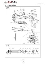
Page 23: ...Fig 35 22 AM TC10626LA 9 2 Turntable assembly ...
Page 24: ...Fig 36 22 AM TC10626LA 9 3 Gearbox motor assembly ...
Page 25: ...24 AM TC10626LA 9 4 Body assembly Fig 37 ...
Page 26: ...25 AM TC10626LA 9 5 Bead Breaker Cylinder Breaker Arm Assembly Fig 38 ...
Page 27: ...26 AM TC10626LA 9 6 Quick inflating system Optional Fig 39 ...
Page 28: ...27 AM TC10626LA 9 7 Simple left help arm Optional Fig 40 INSTALL ...
Page 41: ...40 AM TC10626LA Appendix 1 Electrical Diagram Fig 40 Fig 41 ...


