


186
ASC110 / ASC130 / ASC150
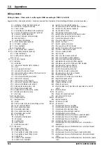
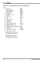
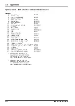
3.8.
Appendixes
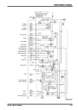
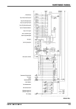
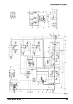
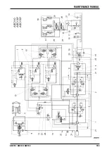
Wiring scheme
Wiring scheme - Chair switch - with engine QSB according to TIER II (4 x ASC)
Legend: (the schematic reflects machine version that includes all controlling elements and accessories)
A1 - Interrupter of direction lights (optional)
A2 - Electronics safeguard traversing
A3 - Travel control
A4 - Controlling unit of differential lock (optional)
A5 - Sensor of longitudinal inclination (optional)
B1 - Sensor of cooling liquid level
B2 - Sensor of hydraulic oil thermometer
B3 - Fuel level sensor
E1 - Instruments illumination
E2, 3 - Front outline lights (optional)
E4, 5 - Tail lights (optional)
E6, 7 - Front headlights
E8, 9 - Rear headlights
E10,11 - Left direction lights (optional)
E12,13 - Right direction lights (optional)
E14 - Cabin illumination
E15 - Safety beacon (optional)
F1-9 - Fuses
F11-16 - Fuses of engine
G1,2 - Batteries
G3 - Alternator
H1 - Indicator of direction lights (optional)
H2 - Horn
H3 - Back-up alarm (optional)
H4 - Indicator of hydraulic oil level
H5 - Indicator of neutral position of the travel control
H6 - Indicator of brake
H7 - Indicator of vibration preselection
H10 - Indicator of charging
H11 - Indicator of air filter clogging
H12 - Indicator of hydraulic filter clogging
H13 - Indicator of differential lock (ASC)
H14 - Stop engine warning lamp - red
H15 - Water in fuel warning lamp
H16 - Engine defect warning lamp - yellow
H17 - Maintenance indicator lamp
K1 - Start relay
K2-9 - Auxiliary relay
K10 - Preheating relay
K11 - Auxiliaries relay
M1 - Starter
M2 - Electric motor of hood & cabin lifting system
M3 - Fan of cabin ventilation
M4 - Front windscreen wiper
M5 - Rear windscreen wiper
M6 - Front windscreen washer
M7 - Rear windscreen washer
M8 - Fan of heating
P2 - Hydraulic oil thermometer
P3 - Fuel gauge
P4 - Speedometer
P5 - Hour counter
Q1 - Battery disconnector
R1,2 - Resistors
R3 - Engine preheating
R4 - Engine speed control
S1 - Push button of cabin lifting system
S2 - Push button of hood lifting system
S3 - Switch box
S4 - Switch of front headlights
S5 - Switch of rear headlights
S6 - Switch of warning lights (optional)
S7 - Change-over switch of direction lights (optional)
S8 - Switch of safety beacon (optional)
S9 - Push button of horn
S11 - Push button of emergency brake
S12 - Switch of back-up alarm (at the travel control)
S13 - Switch of neutral (at the travel control)
S14 - Float of the hydraulic oil tank
S15 - Pressure switch of steering
S16 - Switch - fast travel
S17 - Switch - speed preselector
S18 - Change-over switch of vibration
S19 - Switch of vibration (at the travel control)
S20 - Terminal switch of the gas lever
S21 - Pressure switch of brake
S22 - Chair switch
S23 - Sensor of drum speed (optional)
S24 - Sensor of left wheel speed (optional)
S25 - Sensor of right wheel speed (optional)
S27 - Underpressure switch of air filter clogging
S28 - Underpressure switch of hydraulic filter clogging
S29 - Change-over of cabin ventilation
S30 - Switch of front windscreen wiper
S31 - Switch of rear windscreen wiper
S32 - Push button of windscreen washer
S33 - Change-over switch of fan of heating
S35 - Parking brake push button
S36 - Limit switch of traction spin of the drum
S37 - Engine idle speed switch
S38 - Engine diagnostic switch
S39 - Trouble shooting switch
S40 - Water in fuel sensor
V3 - Blocking diode (only machine with signalling of sound lift
cabin)
V4-7 - Blocking diode
X2-24 - Connectors
X25 - Diagnostic socket (optional)
X27 - Socket of safety beacon
X28-33 - Connectors
X34 - Engine diagnostic
X35-40 - Connectors J1939
X41-42 - Connectors
Y1 - Electromagnetic valve cab lifting
Y2 - Electromagnetic valve cab lowering
Y3 - Electromagnetic valve hood lifting
Y4 - Electromagnetic valve hood lowering
Y6 - Electromagnetic valve of brake
Y7 - Electromagnetic valve of fast travel speed (left wheel)
Y8 - Electromagnetic valve of fast travel speed (drum)
Y9 - Electromagnetic valve of vibration I.
Y10 - Electromagnetic valve of vibration II.
Y11 - Electromagnetic valve of differential lock - LH wheel bac-
kward(opt.)
Y12 - Electromagnetic valve of differential lock - LH wheel forward
(opt.)
Y13 - Servovalve of the pump of travel
Y14 - Electromagnetic valve of fast travel speed (right wheel)
Y15 - Electromagnetic valve of differential lock - RH wheel forward
(opt.)
Y16 - Electromagnetic valve of differential lock - RH wheel backward
(opt.)
Summary of Contents for ASC 130
Page 1: ...Operating manual E ASC 130 Cummins Tier II 5 2006...
Page 4: ...4 ASC 130...
Page 6: ...ASC 130...
Page 12: ...10 ASC 130...
Page 13: ...11 ASC 130 1 SPECIFICATION MANUAL ASC 130...
Page 34: ...32 ASC 130...
Page 35: ...33 ASC 130 SPECIFICATION MANUAL...
Page 36: ...34 ASC 130 N s e t o...
Page 37: ...35 ASC 130 SPECIFICATION MANUAL N s e t o...
Page 38: ...36 ASC 130 N s e t o...
Page 39: ...37 ASC 130 SPECIFICATION MANUAL N s e t o...
Page 40: ...38 ASC 130...
Page 42: ...40 ASC110 ASC130 ASC150 ASC200 ASC250...
Page 56: ...54 ASC110 ASC130 ASC150 ASC200 ASC250...
Page 64: ...62 ASC110 ASC130 ASC150 ASC200 ASC250 2 6 Controls and control devices...
Page 66: ...64 ASC110 ASC130 ASC150 ASC200 ASC250 2 6 Controls and control devices...
Page 68: ...66 ASC110 ASC130 ASC150 ASC200 ASC250 2 6 Controls and control devices...
Page 70: ...68 ASC110 ASC130 ASC150 ASC200 ASC250 2 6 Controls and control devices...
Page 72: ...70 ASC110 ASC130 ASC150 ASC200 ASC250 2 6 Controls and control devices...
Page 87: ...85 ASC110 ASC130 ASC150 ASC200 ASC250 OPERATING INSTRUCTIONS...
Page 122: ...120 ASC110 ASC130 ASC150 ASC200 ASC250 N s e t o...
Page 123: ...121 ASC110 ASC130 ASC150 ASC200 ASC250 OPERATING INSTRUCTIONS N s e t o...
Page 124: ...122 ASC110 ASC130 ASC150 ASC200 ASC250...
Page 125: ...123 ASC110 ASC130 ASC150 3 MAINTENANCE MANUAL ASC 110 ASC 130 and ASC 150 Cummins tier 2...
Page 126: ...124 ASC110 ASC130 ASC150...
Page 134: ...132 ASC110 ASC130 ASC150 3 4 Lubrication and Maintenance Chart...
Page 135: ...133 ASC110 ASC130 ASC150 MAINTENANCE MANUAL...
Page 136: ...134 ASC110 ASC130 ASC150 3 5 Lubrication Chart...
Page 186: ...184 ASC110 ASC130 ASC150 3 6 Individual Operations of Maintenance...
Page 189: ...187 ASC110 ASC130 ASC150 MAINTENANCE MANUAL...
Page 190: ...188 ASC110 ASC130 ASC150 3 8 Appendixes...
Page 191: ...189 ASC110 ASC130 ASC150 MAINTENANCE MANUAL...
Page 193: ...191 ASC110 ASC130 ASC150 MAINTENANCE MANUAL...
Page 195: ...193 ASC110 ASC130 ASC150 MAINTENANCE MANUAL...
Page 196: ...194 ASC110 ASC130 ASC150 3 8 Appendixes N s e t o...
Page 197: ...195 ASC110 ASC130 ASC150 MAINTENANCE MANUAL N s e t o...
Page 198: ...N s e t o...