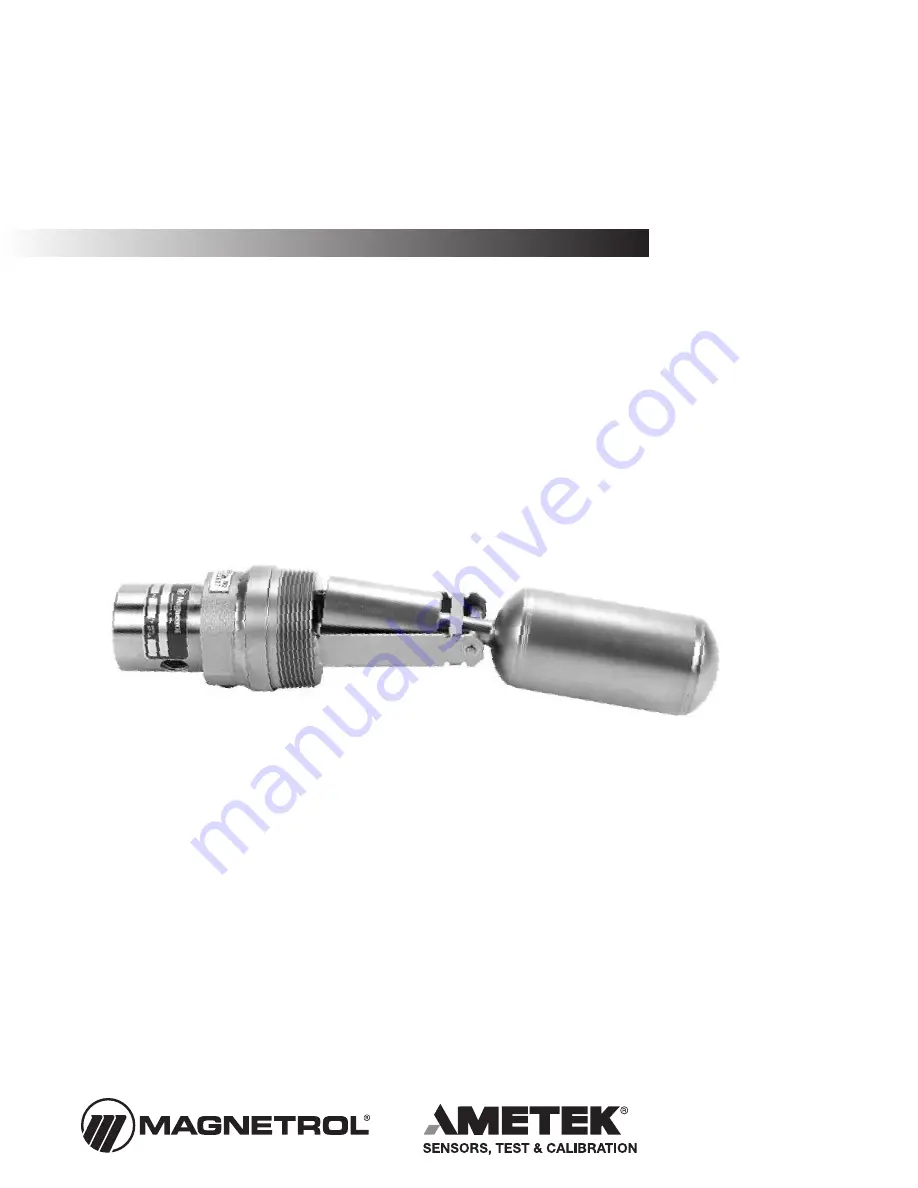
Side
Mounted
Float Level
Switch
Tuffy
®
Liquid Level Controlswith Pneumatic Switch
Installation and Operating Manual
Page 1: ...Side Mounted Float Level Switch Tuffy Liquid Level Controls with Pneumatic Switch Installation and Operating Manual...
Page 2: ...Always shut off the power supply before touching any components WARNING Explosion hazard Do not connect or dis connect equipment unless power has been switched off or the area is known to be non hazar...
Page 3: ...Ensure that the length and inside diameter of the mounting nozzle are sized correctly to allow for switch actuation at design levels Refer to Figure 1 2 Ensure that the mounting nozzle or coupling is...
Page 4: ...ould be done in such a way as to minimize the action of dynamic forces on the float or displacer sensing element Good practice for reducing the likelihood of damage to the control is to equal ize pres...
Page 5: ...he field of the switch mechanism magnet As a result the magnets repel causing the pivot arm and valve plunger to move so that air is allowed to pass from air inlet A to air outlet C As liquid level ri...
Page 6: ...tory or your local representative 3 NEVER use in systems which have excess iron particles in the solution The magnet at the counterweight end of the float can attract the particles which could cause t...
Page 7: ...e 40 to 300 F 40 to 149 C Ambient Temperature Max 100 F 38 C with maximum process temperature Pneumatic Switch Supply Pressure Vacuum to 200 psig 13 8 bar maximum Maximum Leakage Rate 0 5 SCFH 0 015 S...
Page 8: ...aims for misapplication labor direct or consequen tial damage will be allowed Low Voltage Directive For use in Installations Category II Pollution Degree 2 If equipment is used in a manner not specifi...