Page 7
User Guide
Signal Processor
LMG GS
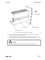
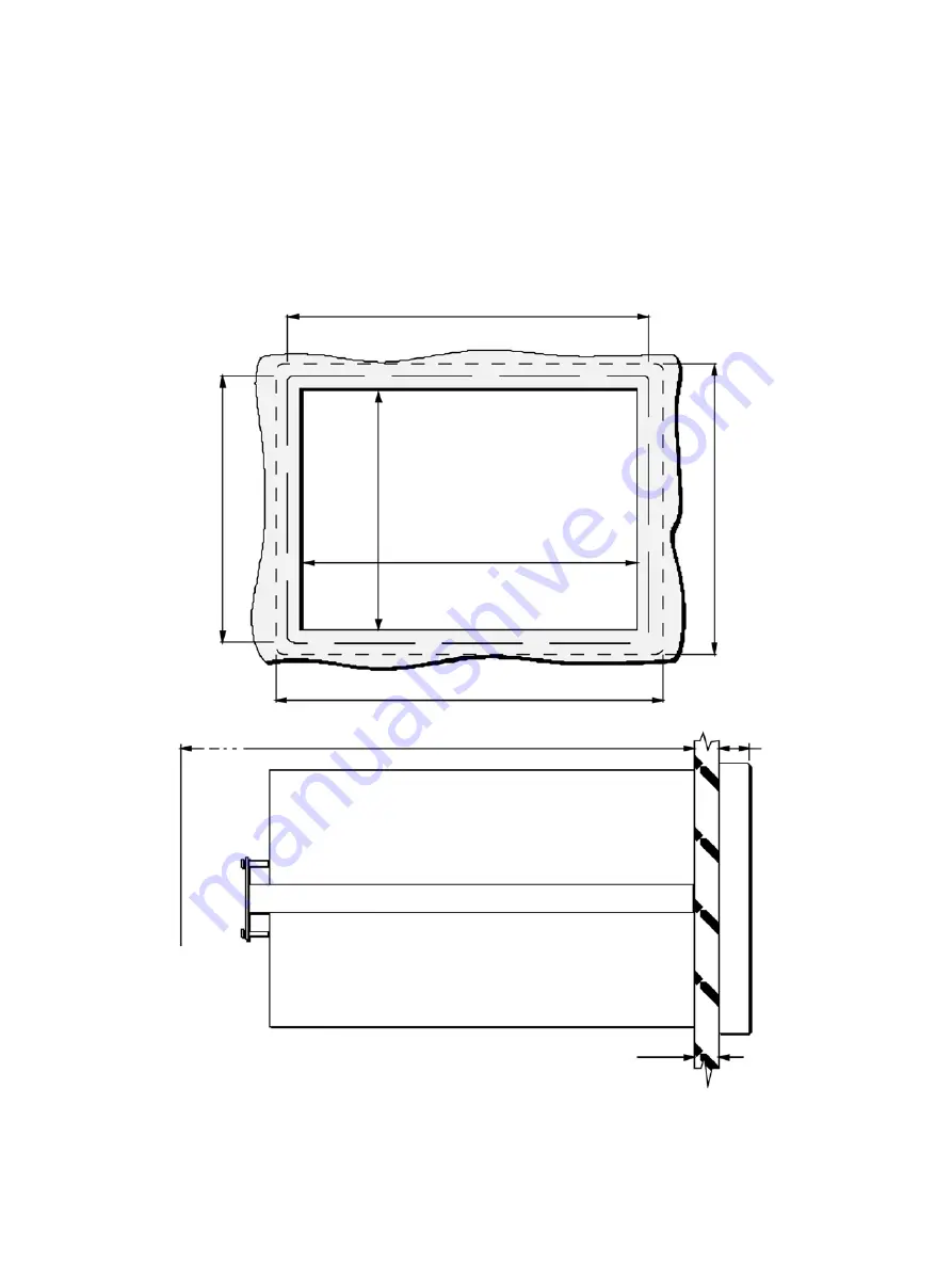
Fig. 2 - Processor installation dimensions
238002
2 Installing the Processor
2.1 Installing the Processor into a Panel
The Landmark Graphic GS processor is designed to be mounted into an
instrument panel. The overall installation dimensions of the processor are
given in Fig. 2.
Processor front bez
el
144mm/5.7in
Processor front bezel 192mm/7.6in
Protection cover 206mm/8.1in
Approximately 400mm/15.8in required for card removal
Protection co
ver 158mm/6.2in
Maximum panel thickness = 13mm/0.5in
186 (+1.1,-0)mm
/7.3 (+.04,-0)in
13
8
(+
1,
-
0)
m
m
/
5.
4
(+
0.
04
,
-0
)i
n
Cut-Out
Mounting
panel
16mm
/0.6in
Summary of Contents for Land LMG GS
Page 2: ......
Page 6: ......
Page 8: ......
Page 12: ...Page 4 Signal Processor User Guide LMG GS...
Page 35: ...Page 27 User Guide Signal Processor LMG GS Fig 20 Access code display 238020...
Page 62: ......


