


ReFlex Power™
Active Loads
M380056-01 Rev L
7-21
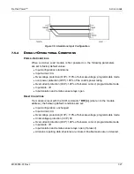
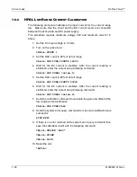
Twisted cable recommended, 25uH max. wire inductance
DC
I
NPUT
P
INOUT
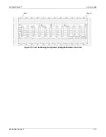
Figure 7-7. DC Input Connector and Wiring Diagram
Table 7-3. DC Input Pinout and Wire Information
Pin
Name
Function
Signal Level
Max Wire
Gauge
D
DCIN
INPUT:INPUT SOURCE
+500V; 500V, MAX TO
CHASSIS
8
B
DCIN_RTN
INPUT: RETURN FOR INPUT SOURCE
DCIN
0V; 500V, MAX TO CHASSIS
8
C
SNS
INPUT; REMOTE SENSE FOR DCIN
+500V; 500V, MAX TO
CHASSIS
16
A
SNS_RTN
INPUT REMOTE SENSE FOR
DCIN_RTN
0V; 500V, MAX TO CHASSIS
16
DC
I
NPUT
C
ONNECTOR
A
CCESSORIES
AMETEK P/N 5380452-01, Load Module, 9ft. Unterminated DC Input Cable
Assembly
R
EMOTE
S
ENSE
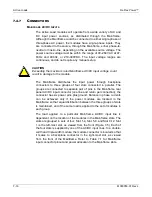
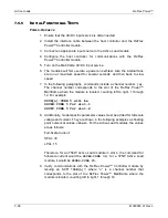
Remote sensing is used to compensate for the voltage drop that
occurs across the wires connecting the source to the input of the
Active Load modules. A separate pair of wires is routed to measure
the voltage at the source terminals where precise measurement of the
output voltage is desired.
The remote sense leads are connected at the DC INPUT connector
on the front panel of the modules. Refer to the section,
DC Inputs
, for
information on connector pinout. Connect the SNS terminal to the load
terminal connected to the module DCIN terminal, and the SNS-RTN
terminal to the load terminal connected to DCIN-RTN terminal.
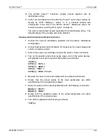
Special care is required in routing the sensing leads to prevent noise
pickup or coupling to the power leads; refer to the section, Noise and
Impedance Effects. The sense leads should be a twisted-pair of AWG
#16-20 wire, and may require shielding in high noise environments.
Connect the shield to the shield ground terminal, CHAS-GND, of the
DC INPUT connector, as required to maximize its effectiveness.
Summary of Contents for Elgar ReFlex Power
Page 1: ...M380056 01 Rev L www programmablepower com ReFlex Power Operation Manual...
Page 2: ......
Page 3: ......
Page 4: ......
Page 6: ...ii This page intentionally left blank...
Page 8: ...iv This page intentionally left blank...
Page 10: ...vi This page intentionally left blank...
Page 21: ...M380056 01 Rev L xvii This page intentionally left blank...
Page 22: ......
Page 85: ...ReFlex Power Controller ReFlex Power 3 22 M380056 01 Rev L This page intentionally left blank...
Page 89: ...AC Power Supplies ReFlex Power 4 4 M380056 01 Rev L Figure 4 1 ACPS Module Front Panel 875VA...
Page 120: ...ReFlex Power AC Power Supplies M380056 01 Rev L 4 35 Figure 4 11 Parallel Output Configuration...
Page 147: ...AC Power Supplies ReFlex Power 4 62 M380056 01 Rev L RST n...
Page 157: ...AC Power Supplies ReFlex Power 4 72 M380056 01 Rev L 26 Reset the unit RST n...
Page 274: ...ReFlex Power DC Power Supplies M380056 01 Rev L 6 71 18 Turn off the output RST n...
Page 275: ...DC Power Supplies ReFlex Power 6 72 M380056 01 Rev L This page intentionally left blank...
Page 279: ...Active Loads ReFlex Power 7 4 M380056 01 Rev L Figure 7 1 LPAL 375W Front Panel...
Page 280: ...ReFlex Power Active Loads M380056 01 Rev L 7 5 Figure 7 2 HPAL 750W Front Panel...
Page 281: ...Active Loads ReFlex Power 7 6 M380056 01 Rev L Figure 7 3 Typical Active Load Rear Panel...
Page 359: ...Active Loads ReFlex Power 7 84 M380056 01 Rev L This page intentionally left blank...


