3 - 1
User Guide
LMG MkII
Signal Processor
1
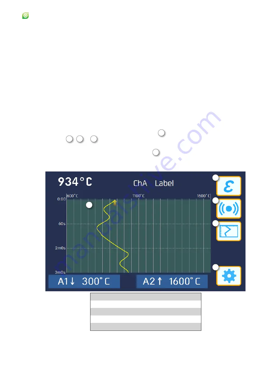
Touch screen display
2
Emissivity adjustment ‘Quick button’
3
Alarm settings ‘Quick button’
4
Display selector ‘Quick button’
5 Settings menu
Fig. 3-1 Front panel touchscreen display and controls
3
Using the Processor
Once the processor has been installed in its chosen location, it must be
connected to at least one System 4 thermometer as a minimum, and to a
suitable 24 V dc power supply (See Fig 2-14).
Once the processor is connected to a System 4 thermometer, it must be
configured for use with that thermometer. The temperature measurement
system (i.e. processor and thermometer) is configured, via the processor’s
menu system, using the touchscreen display on the front panel. The location
of the controls is given in Fig. 3-1.
3.1 Getting Started (accessing the menu system)
When the Landmark Graphic MkII processor is connected to a System 4
thermometer and a suitable power supply, the processor display will be
similar to that shown in Fig. 3-1.
On the left is the Temperature Display area
1
. On the right are 3 ‘Quick’
buttons 2
,
3
&
4
, to access the commonly adjusted parameters quickly.
To access the configuration menus, and set up your system to your particular
requirements, press the
Settings
button
5
1
2
3
4
5
Summary of Contents for LMG MkII
Page 6: ...INTRODUCTION 1 ...
Page 10: ...INSTALLING THE PROCESSOR 2 ...
Page 14: ...User Guide 2 4 Signal Processor LMG MkII Fig 2 4 LMG MkII Electrical System Overview ...
Page 22: ...3 USING THE PROCESSOR ...
Page 44: ...TIME FUNCTION PROCESSING 4 ...
Page 50: ...SERIAL COMMUNICATIONS 5 ...
Page 62: ...Signal Processor LMG MkII Blank ...
Page 63: ...EXTERNAL I O MATHS FUNCTIONS 6 ...
Page 64: ...Signal Processor LMG MkII Screws A Fig 6 1 Location of screws on back panel Screws A ...
Page 88: ...MAINTENANCE 7 ...
Page 92: ...User Guide 7 4 Signal Processor LMG MkII Fig 7 3 USB Export Data option ...


