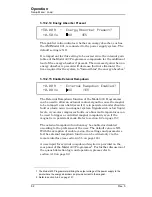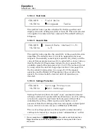
Rev. 5
53
Operation
Setup Menu : Load
by using either the numeric keypad per section 3.3 on page 29 or
the fine adjust knob (section 3.4 on page 31). The valid range is
from 0.0 to 100.0%. The default value is 0.0% unless preset by AMI
to match a specific superconducting magnet.
Superconducting magnets
without a persistent switch
require
1
a
specific Model 430 Programmer stability setting based on the
magnet inductance as follows:
For magnet inductance
<=
100 Henries (H):
Stability Setting = (100 - H)
For magnet inductance
>
100 Henries:
Stability Setting = 0
The graph below may be used as a guide to set the stability setting
for magnets
with a persistent switch
installed and inductance of
less than 3 henries. Magnets with an inductance of greater than 3
henries that have a persistent switch installed should operate with
a stability setting of 0.0%.
The Model 430 Programmer internal control loop gain is
proportional to the multiplier (100% – [Stability Setting]), except
that for a Stability of 100% the multiplier is set to a low non-zero
value suitable for controlling current in a short circuit. For this
1. Effective with Model 430 firmware version 1.62.
y
g
g
0
10
20
30
40
50
60
70
80
90
100
0
1
2
3
4
5
6
7
Inductance (H)
Stab
ility Settin
g
(%)
Figure 3-9.
Stability Setting vs. Magnet (with PSwitch) Inductance
Model 430 Stability Setting vs. Magnet Inductance
(for Magnets with Persistent Switch)
Summary of Contents for 05100PS-430-601
Page 2: ......
Page 10: ...x Rev 5 List of Figures ...
Page 12: ...xii Rev 5 List of Tables ...
Page 18: ...xviii Rev 5 Foreword Safety Summary ...
Page 30: ...12 Rev 5 Introduction Operating Characteristics ...
Page 42: ...24 Rev 3 Installation Power Up Procedure ...
Page 114: ...96 Rev 5 Operation Summary of Operational Limits ...
Page 156: ...138 Rev 5 Remote Interface Reference Error Messages ...
Page 168: ...150 Rev 5 Service Return Authorization ...
Page 226: ...208 Rev 5 Index ...


