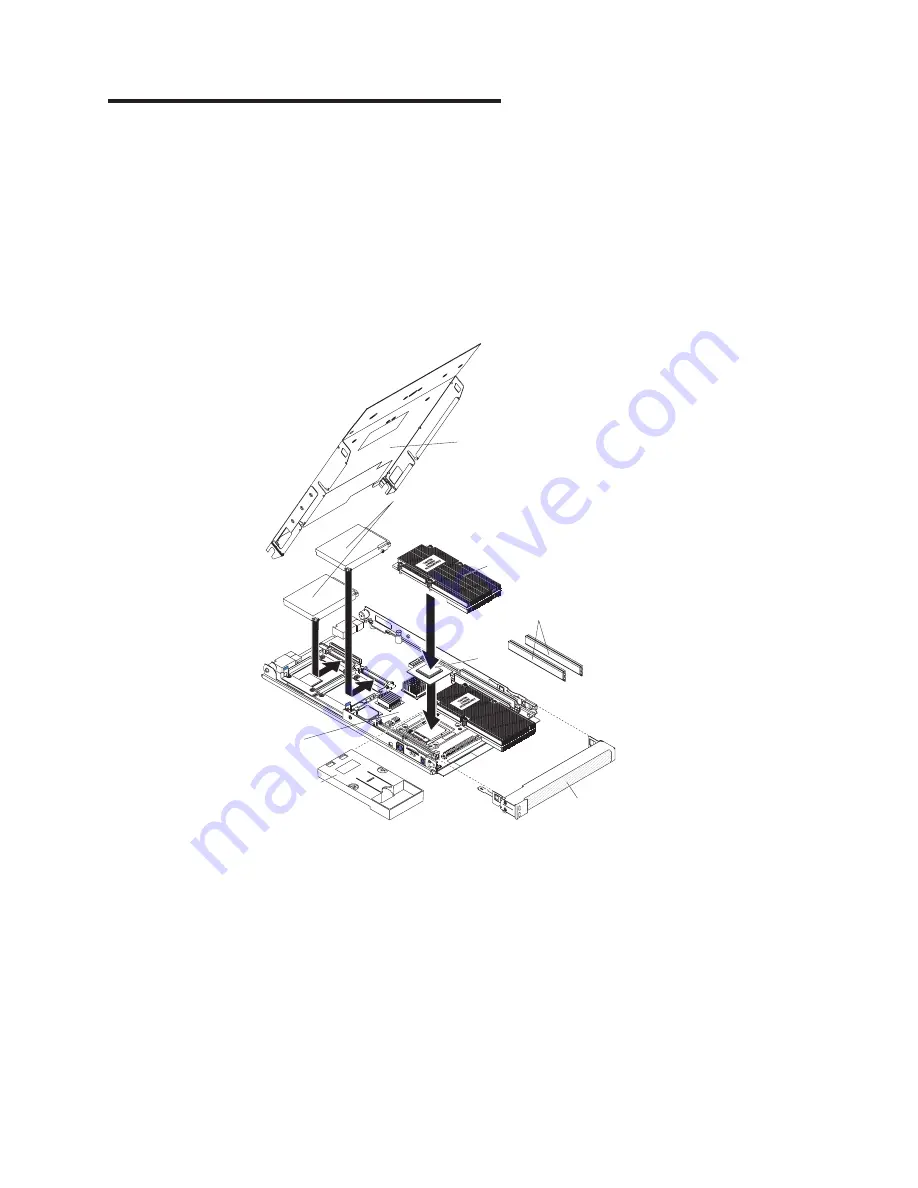
background image

Chapter


3.


Parts


listing,


Type


8850


The


following


replaceable


components


are


available


for


the


LS20


Type


8850


blade


server.


To


check


for


an


updated


parts


listing


on


the


Web,


complete


the


following


steps:


1.


Go


to


http://www.ibm.com/support/


2.


Under


Search


technical


support

,


type


8850


and


click


Search

.


3.


Under


Document


type,


select


Parts


information


and


click


Go

.

Note:


The


illustrations


in


this


document


might


differ


slightly


from


your


hardware.


1

2

3

5

6

7

4

8


©


Copyright


IBM


Corp.


2005


53

Summary of Contents for Opteron LS20

Page 1: ...AMD Opteron LS20 Type 8850 for IBM BladeCenter Problem Determination and Service Guide...

Page 2: ......

Page 3: ...AMD Opteron LS20 Type 8850 for IBM BladeCenter Problem Determination and Service Guide...

Page 4: ...al information in Appendix B Notices on page 91 Third Edition February 2005 Copyright International Business Machines Corporation 2005 All rights reserved US Government Users Restricted Rights Use dup...

Page 5: ...bout the checkout procedure 26 Performing the checkout procedure 27 Troubleshooting tables 27 CD or DVD drive problems 28 Diskette drive problems 29 General problems 29 Hard disk drive problems 30 Int...

Page 6: ...ing FRUs 76 Microprocessor 76 System board assembly 82 Chapter 5 Configuration information and instructions 83 Updating the firmware 83 Configuring the blade server 84 Using the Configuration Setup Ut...

Page 7: ...n tuotteen lue turvaohjeet kohdasta Safety Information Avant d installer ce produit lisez les consignes de s curit Vor der Installation dieses Produkts die Sicherheitshinweise lesen Prima di installar...

Page 8: ...is not damaged loose or broken and observe any sharp edges 3 Check the power cord v Make sure that the third wire ground connector is in good condition Use a meter to measure third wire ground continu...

Page 9: ...ailable to turn off the power if necessary When you are working with powered on electrical equipment use only one hand Keep the other hand in your pocket or behind your back to avoid creating a comple...

Page 10: ...ater or structural damage v Disconnect the attached power cords telecommunications systems networks and modems before you open the device covers unless instructed otherwise in the installation and con...

Page 11: ...ces or regulations Statement 3 CAUTION When laser products such as CD ROMs DVD drives fiber optic devices or transmitters are installed note the following v Do not remove the covers Removing the cover...

Page 12: ...he power switch on the power supply do not turn off the electrical current supplied to the device The device also might have more than one power cord To remove all electrical current from the device e...

Page 13: ...us voltage current and energy levels are present inside any component that has this label attached There are no serviceable parts inside these components If you suspect a problem with one of these par...

Page 14: ...xii AMD Opteron LS20 Type 8850 for IBM BladeCenter Problem Determination and Service Guide...

Page 15: ...all supported options and how to configure the server v Safety Information This document is in Portable Document Format PDF on the Documentation CD It contains translated caution and danger statements...

Page 16: ...roblem situations v Attention These notices indicate potential damage to programs devices or data An attention notice is placed just before the instruction or situation in which damage could occur v C...

Page 17: ...sion card interface v Baseboard management controller BMC with IPMI firmware v ATI Radeon 7000M video controller v LSI 1020 SCSI controller v Light path diagnostics v Local service processor BMC v RS...

Page 18: ...g sequence to switch keyboard mouse and video control between blade servers NumLock NumLock blade_server_number Enter Where blade_server_number is the two digit number for the blade bay in which the b...

Page 19: ...on the blade server Activity LED When this green LED is lit it indicates that there is activity on the hard disk drive or network Location LED When this blue LED is lit it has been turned on by the s...

Page 20: ...shing slowly the Wake on LAN feature can turn on the blade server if the Wake on LAN feature has not been disabled through the management module Turning off the blade server When you turn off the blad...

Page 21: ...t 2 and heat sink filler Battery BH1 Control panel connector SCSI connector 1 J12 SCSI connector 0 J11 I O expansion option connector J13 I O expansion option connector J10 System board jumpers The fo...

Page 22: ...R47 future use Light path diagnostics panel Microprocessor 1 error LED CR54 Microprocessor 2 error LED CR50 DIMM 1 error LED CR52 DIMM 3 error LED CR46 DIMM 4 error LED CR49 DIMM 2 error LED CR48 The...

Page 23: ...omponents of the blade server These programs are stored in read only memory ROM on the blade server See Diagnostic programs messages and error codes on page 43 for more information POST When you turn...

Page 24: ...performed only by a trained service technician Beep code Description Action 1 1 2 Microprocessor register test failed 1 Reseat the following components a Trained service technician only Microprocesso...

Page 25: ...ice technician only System board assembly 1 3 1 First 64K RAM test failed 1 Reseat the DIMMs 2 Replace the following components one at a time in the order shown restarting the server each time a DIMMs...

Page 26: ...chnician only System board assembly 2 2 4 CMOS configuration information validation failed 1 Reseat the battery 2 Replace the following components one at a time in the order shown restarting the serve...

Page 27: ...server each time a DIMMs b Trained service technician only System board assembly 3 1 4 Time of day clock failed 1 Reseat the battery 2 Replace the following components one at a time in the order shown...

Page 28: ...ladeCenter unit 2 Reseat the DIMMs 3 Replace the following components one at a time in the order shown restarting the server each time a DIMMs b Trained service technician only System board assembly 3...

Page 29: ...ng the server each time a DIMMs b Trained service technician only System board assembly One continuous beep Microprocessor error 1 Reseat the following components a Trained service technician only Mic...

Page 30: ...field replaceable units FRU v If an action step is preceded by Trained service technician only that step must be performed only by a trained service technician No beep symptom Description Action No be...

Page 31: ...anagement module event log in your BladeCenter unit lists messages according to the position of the blade server in the blade bays If a blade server is moved from one bay to another the management mod...

Page 32: ...When the prompt Press F1 for Configuration Setup appears press F1 If you have set a power on password you must type the password and press Enter to start the Configuration Setup Utility program 3 Sele...

Page 33: ...the Configuration Setup Utility program select Load Default Settings and save the settings 2 Reseat the following components a Battery b Failing device 3 Replace the following components one at a tim...

Page 34: ...only Replace the microprocessor 201 Memory test error 1 Update BIOS code and rerun diagnostics 2 Reseat the DIMMs 3 Replace the following components one at a time in the order shown restarting the ser...

Page 35: ...starting the server each time a Keyboard b Trained service technician only System board assembly 303 Keyboard controller error Trained service technician only Replace the system board assembly 602 Inv...

Page 36: ...1 Reseat the external cable on the serial port 2 Run the Configuration Setup Utility program 3 Trained service technician only Replace the system board assembly 1162 Serial port configuration conflic...

Page 37: ...alid boot sector 1 Make sure that a bootable operating system is installed 2 Run the Fixed Disk diagnostic test 3 Reseat the hard disk drive 4 Replace the following components one at a time in the ord...

Page 38: ...ce technician only System board assembly e Battery 8603 Pointing device error 1 Reseat the pointing device 2 Replace the following components one at a time in the order shown restarting the server eac...

Page 39: ...ed service technician only Replace microprocessor x 012981xx Processor patch microcode update failed 1 Flash the BIOS code 2 Trained service technician only Reseat microprocessor x 3 Trained service t...

Page 40: ...next time you run the diagnostic programs Exception If there are multiple error codes or light path diagnostics LEDs that indicate a microprocessor error the error might be in a microprocessor or in a...

Page 41: ...ound and are there readable instructions on the main menu v No Find the failure symptom in Troubleshooting tables if necessary see Solving undetermined problems on page 51 v Yes Run the diagnostic pro...

Page 42: ...r DVD drive as dev sr0 instead of dev cdrom Establish a link between dev sr0 and dev cdrom as follows 1 Enter the following command rm dev cdrom ln s dev sr0 dev cdrom 2 Insert the following line in t...

Page 43: ...ity program v The software program is working properly v The cable is installed correctly in the proper orientation 2 To prevent diskette drive read write errors be sure the distance between monitors...

Page 44: ...new one A hard disk drive passes the Fixed Disk diagnostics test but the problem remains Run the SCSI Fixed Disk diagnostic test Note This test is not available on servers that have RAID arrays or ser...

Page 45: ...connected to the shared BladeCenter monitor v The mouse or pointing device cable is securely connected to the BladeCenter management module and that the keyboard and mouse cables are not reversed v T...

Page 46: ...for error message 289 v If the DIMM was disabled by a system management interrupt SMI replace the DIMM v If the DIMM was disabled by the user or by POST a Start the Configuration Setup Utility program...

Page 47: ...ring POST followed by a blank display screen If this occurs and the Boot Fail Count feature in the Start Options of the Configuration Setup Utility program is set to Enabled its default setting you mu...

Page 48: ...screen 1 If the wrong language is displayed update the firmware or operating system with the correct language in the blade server that has ownership of the monitor 2 Replace the monitor 3 Trained ser...

Page 49: ...talled 4 Replace the device that you just installed Power error messages v Follow the suggested actions in the order in which they are listed in the Action column until the problem is solved v See Cha...

Page 50: ...ystem over recommended 5V fault 1 Reseat the blade server 2 Replace the blade server VRM voltage over recommended tolerance 1 Reseat the blade server 2 Replace the blade server System under recommende...

Page 51: ...Local power control for the blade server is enabled use the BladeCenter management module Web interface to verify or the blade server was instructed through the management module Web interface or IBM...

Page 52: ...rvice technician only that step must be performed only by a trained service technician Symptom Action The ServerGuide Setup and Installation CD will not start v Make sure that the CD or DVD drive is a...

Page 53: ...ed service technician only that step must be performed only by a trained service technician Symptom Action You suspect a software problem 1 To determine whether the problem is caused by the software m...

Page 54: ...iew light path diagnostics LEDs read the safety information that begins on page v and Handling static sensitive devices on page 58 If an error occurs view the light path diagnostics LEDs in the follow...

Page 55: ...M 2 error LED CR48 The following illustration shows LEDs on the light path diagnostics panel on the system board MIS NMI SBRD TEMP NMI error LED Microprocessor mismatch error LED System board error LE...

Page 56: ...t or replace one DIMM at a time until the error goes away Refer to the Hardware Maintenance Manual and Troubleshooting Guide or Problem Determination and Service Guide for your BladeCenter unit type f...

Page 57: ...s text messages and error codes are displayed on the screen and are saved in the test log A diagnostic text message or error code indicates that a problem has been detected to determine what action yo...

Page 58: ...uttons to select categories All other mouse selectable functions are available through function keys To view server configuration information such as system configuration memory contents interrupt req...

Page 59: ...e a CRU or FRU These numbers appearing in the central position of the code have the following meanings 000 The blade server passed the test Do not replace a CRU or FRU 195 The Esc key was pressed to e...

Page 60: ...ram and run the test again see Configuration Setup Utility menu choices on page 85 001 xxx 000 Failed core tests Trained service technician only Replace the system board assembly 001 xxx 001 Failed co...

Page 61: ...ates failure in I2C bus test 1 Remove the blade server from the BladeCenter unit wait 30 seconds reseat it in the BladeCenter unit and run the test again 2 Update the BMC firmware see Updating the fir...

Page 62: ...oprocessor 1 2 Replace the following components one at a time in the order shown restarting the server each time a Trained service technician only Microprocessor 1 b Trained service technician only Sy...

Page 63: ...t the error and automatically switch to the backup page to start the server If this happens a POST message Booted from backup POST BIOS image is displayed The backup page version may not be the same v...

Page 64: ...blade server in the BladeCenter unit then restart the blade server The system starts up Statement 21 CAUTION Hazardous energy is present when the blade server is connected to the power source Always...

Page 65: ...ck the LEDs on all the power supplies of the BladeCenter unit where the blade server is installed If the LEDs indicate that the power supplies are working correctly and reseating the blade server does...

Page 66: ...e Is the failure repeatable Has the current server configuration ever worked What changes if any were made before it failed Is this the original reported failure or has this failure been reported befo...

Page 67: ...pdated parts listing on the Web complete the following steps 1 Go to http www ibm com support 2 Under Search technical support type 8850 and click Search 3 Under Document type select Parts information...

Page 68: ...r all models 31R3399 4 Microprocessor with heat sink Opteron 246 2 0 1 MB model 51x CTO 31R3444 4 Microprocessor with heat sink Opteron 250 2 4 1 MB model 71x 72x CTO 31R3394 4 Microprocessor with hea...

Page 69: ...nsion card option 39M4630 Grease heat sink all models 59P4740 Kit miscellaneous parts all models v Screw M3 5 x 6 Phillips pan head system board v Light pipe hard disk drive LEDs v Screw M3 x 3 Philli...

Page 70: ...56 AMD Opteron LS20 Type 8850 for IBM BladeCenter Problem Determination and Service Guide...

Page 71: ...This information will help you work safely v Observe good housekeeping in the area where you are working Place removed covers and other parts in a safe place v Back up all important data before you m...

Page 72: ...e end and firmly connected to the ESD connector on the front or back of the BladeCenter T unit v Limit your movement Movement can cause static electricity to build up around you v Handle the device ca...

Page 73: ...1 If the blade server is operating shut down the operating system then press the power control button behind the blade server control panel door to turn off the blade server see Turning off the blade...

Page 74: ...in the same blade bay from which you removed it Some blade server configuration information and update options are established according to bay number Reinstalling a blade server into a different blad...

Page 75: ...you have other blade servers to install do so now Note Reinstall the bezel assembly on the BladeCenter T unit after you have finished installing the blade servers see the BladeCenter T Types 8720 and...

Page 76: ...enter unit remove it see Removing and installing the blade server in a BladeCenter unit on page 59 for instructions 3 Carefully lay the blade server down on a flat non conductive surface with the cove...

Page 77: ...idelines on page 57 2 If you removed the blade server bezel assembly replace it now see Removing and replacing the bezel assembly on page 64 for instructions 3 Lower the cover so that the slots at the...

Page 78: ...approximately 1 2 cm 0 5 inch 4 Disconnect the control panel cable from the control panel connector 5 Pull the bezel assembly away from the blade server 6 Store the bezel assembly in a safe place To...

Page 79: ...elines on page 57 2 Shut down the operating system turn off the blade server and remove the blade server from the BladeCenter unit See Removing and installing the blade server in a BladeCenter unit on...

Page 80: ...the drive 2 Place the drive into the hard disk drive tray and push it toward the rear of the drive into the connector until the drive moves past the lever at the front of the tray 3 Install the blade...

Page 81: ...is installed you can only install DIMMs in the DIMM connectors that are associated with the microprocessor v When you install memory you must install a pair of matched DIMMs v Both DIMMs in a pair mu...

Page 82: ...J30 DIMM 1 J31 DIMM 4 J2 DIMM 3 J4 Microprocessor 1 Microprocessor 2 6 To remove a DIMM repeat the following steps for each DIMM that you want to remove Attention Opening both DIMM retaining clips at...

Page 83: ...the connector retaining clips are in the fully open position Retaining clip DIMM b Turn the DIMM so that the DIMM keys align correctly with the connector on the system board Attention To avoid breakin...

Page 84: ...lade server from the BladeCenter unit See Removing and installing the blade server in a BladeCenter unit on page 59 for instructions 3 Carefully lay the blade server on a flat non conductive surface 4...

Page 85: ...nsion card b Slide the notch in the narrow end of the card into the raised hook on the tray then gently pivot the card into the expansion card connectors 2 Install the blade server cover see Operating...

Page 86: ...ns 3 Carefully lay the blade server on a flat non conductive surface 4 Open the cover see Operating the blade server cover on page 62 for instructions Expansion card Expansion card tray P R E S S H E...

Page 87: ...d drive tray 2 Orient the expansion card and slide the notch in the narrow end of the card into the raised hook on the tray then gently pivot the wide end of the card into the expansion card connector...

Page 88: ...ommended by the manufacturer If your system has a module containing a lithium battery replace it only with the same module type made by the same manufacturer The battery contains lithium and can explo...

Page 89: ...on the side opposite the battery clip b Press the battery down into the socket until it clicks into place Make sure that the battery clip holds the battery securely 3 Install the blade server cover se...

Page 90: ...sor Notes v The heat sink FRU is packaged with the thermal grease applied to the underside This thermal grease is not available as a separate FRU The heat sink must be replaced when new grease is requ...

Page 91: ...he other screws will help to break the thermal bond that adheres the heat sink to the microprocessor b Gently pull the heat sink off of the microprocessor Attention Do not use any tools or sharp objec...

Page 92: ...Failure to do so might result in permanent damage to the microprocessor microprocessor socket and system board Microprocessor locking lever Microprocessor socket Microprocessor v Avoid touching the co...

Page 93: ...cking lever Locking lever retainer tab Attention v You must ensure that the locking lever on the microprocessor socket is in the fully open position before you install the microprocessor into the micr...

Page 94: ...iangle on the corner of the microprocessor with the triangle on the corner of the socket and make sure that the pin patterns of the microprocessor and microprocessor socket match then carefully press...

Page 95: ...ews until they are tight Do not overtighten the screws by using excessive force If you are using a torque wrench tighten the screws to 1 00 to 1 26 Newton meters Nm 8 85 to 11 15 inch pounds Attention...

Page 96: ...page 64 6 Remove any of the installed components listed below from the system board assembly then place them on a non conductive surface or install them on the new system board assembly v I O expansio...

Page 97: ...kette RDM Update Xpress Management module Web interface Switch module Web interface Switch module Telnet interface BIOS code Yes Yes Yes No No No Diagnostic code Yes Yes 1 Yes No No No Service process...

Page 98: ...the RDM program or for updated information about RDM and information about purchasing the software go to http www ibm com pc ww eserver xseries systems_management index html For information about sett...

Page 99: ...choices might differ slightly from these descriptions v System Summary v System Information Product Data v Devices and I O Ports v Date and Time v System Security v Start Options v Advanced Setup Memo...

Page 100: ...t install a device driver to enable the blade server operating system to address the Ethernet controllers For device drivers and information about configuring the Ethernet controllers see the Broadcom...

Page 101: ...d with the switch module in I O module bay 1 The other Ethernet controller in the blade server is associated with the switch module in I O module bay 2 If you have installed an expansion card on a bla...

Page 102: ...88 AMD Opteron LS20 Type 8850 for IBM BladeCenter Problem Determination and Service Guide...

Page 103: ...roblems without outside assistance by following the troubleshooting procedures that IBM provides in the online help or in the publications that are provided with your system and software The informati...

Page 104: ...information about which products are supported by Support Line in your country or region see http www ibm com services sl products For more information about Support Line and other IBM services see h...

Page 105: ...TY OF ANY KIND EITHER EXPRESS OR IMPLIED INCLUDING BUT NOT LIMITED TO THE IMPLIED WARRANTIES OF NON INFRINGEMENT MERCHANTABILITY OR FITNESS FOR A PARTICULAR PURPOSE Some states do not allow disclaimer...

Page 106: ...and Windows NT are trademarks of Microsoft Corporation in the United States other countries or both UNIX is a registered trademark of The Open Group in the United States and other countries Java and a...

Page 107: ...bility and fitness for a particular purpose These products are offered and warranted solely by third parties IBM makes no representations or warranties with respect to non IBM products Support if any...

Page 108: ...nvironment products batteryrecycle shtml or contact your local waste disposal facility In the United States IBM has established a return process for reuse recycling or proper disposal of used IBM seal...

Page 109: ...stallation CD 83 Configuration Setup Utility program 83 84 configuring the blade server 84 configuring your server 83 connectors battery 7 I O expansion card 7 connectors continued memory 7 microproce...

Page 110: ...keyboard problems 31 L LEDs activity 5 blade error 5 control panel 4 error locations 40 information 5 light path diagnostics viewing without power 40 light path locations 40 location 5 power on 5 sys...

Page 111: ...board assembly 82 S SCSI error messages 50 SCSI hard disk drive installing 66 removing 65 SCSI RAID configure an array 87 ServerGuide problems 38 Setup and Installation CD 83 service processor error c...

Page 112: ...98 AMD Opteron LS20 Type 8850 for IBM BladeCenter Problem Determination and Service Guide...

Page 113: ......

Page 114: ...Part Number 24R9677 Printed in USA 1P P N 24R9677...

Reviews: