


20 Gear Drive, Plymouth Ind. Park, Terryville, CT 06786
Tel: (860) 585-1254 Fax: (860) 584-1973 http://www.amci.com
NR60E2 User Manual
NR60 S
PECIFICATIONS
15
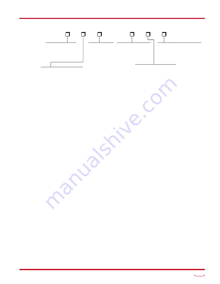
Part Number Description
Figure R1.5 Part Number Description
Available Data
All NR60E2 encoders offer position and velocity data that can be scaled with the programmable parameters
as described in the following section. The position data can also be preset which allows you to align the posi-
tion data with your machine position without having to physically rotate the shaft.
Programmable Parameters
The following parameters are available on all NR60E2 encoders. Units configured for the PROFINET proto-
col, use encoder objects that are defined by these protocols. Therefore, these units have additional parameters
that are protocol specific. These parameters are explained in the PROFINET protocol section,
Count Direction
This parameter is called
Code Sequence
in PROFINET systems. This parameter allows you to set the direc-
tion of shaft rotation needed to produce increasing counts. The default is CW when looking at the shaft.
Effects of Reversing Count Direction
Changing the
Count Direction
parameter changes the way the position value is calculated. When you reverse
the count direction, the position changes from your current position value to (Maximum number of counts –
current position value). For example, assume a 30 bit NR60E2 with its default of 65,536 counts per turn. If
the current position value is 100,000 and you change the Direction Counting Toggle parameter, the current
position will change to (2
30
– 100,000 = 1,073,741,824 – 100,000) = 1,073,641,824.
Most applications do not require you to change the count direction after the machine is setup, so the count
direction is typically set before the position value is preset.
Changing the count direction on your machine while maintaining the current position value is a three step
process. First, read and store the current position value from the NR60E2. Second, change the
Count Direc-
tion
value. Third, write the stored position value back to the NR60E2 as a preset value.
CONNECTOR TYPE
01 = M12 Connectors
(2) 4 pin Female D-Type: Network
(1) 4 pin Male A-Type: Power
NR60E2 –
HOUSING
F1 = Square Flange
S1 = 58 mm Servo Mount
H1 = 63 mm Blind Shaft Mount
OUTPUT CONFIG.
1 = 16 bit Single Turn
2 = 28 bit (12+16) Multi-Turn
3 = 30 bit (14+16) Multi-Turn
–
SHAFT SEAL & BODY
B = Nitrile Seal, Aluminum Body
V = Viton Seal, Aluminum Body
C = Viton Seal, Stainless Steel Body
CONNECTOR
E = End Connector Location
S = Side Connector Location
†
†
Stainless Steel Body only available
with End Connector Location
SHAFT DIA.
Standard Shaft
1 = 0.375" Dia.
2 = 0.250" Dia.
3 = 6 mm Dia.
4 = 10 mm Dia.
1 = 0.375" Dia.
2 = 10 mm Dia.
4 = 0.500" Dia
Blind Shaft Hole
6 = 12 mm Dia.
Summary of Contents for NR60E2
Page 1: ...MICRO CONTROLS INC ADVANCED U s e r M anual E2 Technology E2 Technology Manual 940 0D161...
Page 6: ...TABLE OF CONTENTS NR60E2 User Manual ADVANCED MICRO CONTROLS INC 6 Notes...
Page 20: ...NR60 SPECIFICATIONS NR60E2 User Manual ADVANCED MICRO CONTROLS INC 20 Notes...
Page 44: ...PROTOCOL SPECIFIC INFORMATION NR60E2 User Manual ADVANCED MICRO CONTROLS INC 44 Notes...
Page 52: ...IMPLICIT COMMUNICATIONS WITH AN EDS EtherNet IP Protocol ADVANCED MICRO CONTROLS INC 52 Notes...
Page 58: ...IMPLICIT COMMUNICATIONS WITHOUT EDS EtherNet IP Protocol ADVANCED MICRO CONTROLS INC 58 Notes...
Page 70: ...CIP POSITION SENSOR OBJECT EtherNet IP Protocol ADVANCED MICRO CONTROLS INC 70 Notes...
Page 90: ...PROFINET CYCLIC DATA FORMATS PROFINET Protocol ADVANCED MICRO CONTROLS INC 90 Notes...
Page 98: ...LEADERS IN ADVANCED CONTROL PRODUCTS ADVANCED MICRO CONTROLS INC...