Input Data Format
ADVANCED MICRO CONTROLS INC.
6
74
Status Word 0 (continued)
Bit Values
Bit 15: Acknowledge Bit.
Set to ‘1’ in response to accepting a command block with its Transmit bit set to ‘1’.
The Acknowledge bit will reset to ‘0’ in response to the Transmit bit being reset to ‘0’.
Bit 14: Heartbeat Bit.
This bit changes state every 500 milliseconds and can be used to verify the health of
the ANS1 and active communications between the ANS1 and your host controller.
Bit 13: Hardware Fault.
Most common cause is an error in the checksum of the program last read from
memory. This fault also is used to indicate a communications error between modules in an AnyNET-
I/O Stack, or errors in communicating with the interface to the industrial (host) network.
Bit 12: Resolver Fault.
This error will only occur if the resolver input is used for position feedback. The
ANS1 cannot decode the position from the attached resolver. This error is typically caused by
cabling problems. Refer to the Installation chapter, starting with the
section on
page 41. AMCI also has an FAQ on our website that will help you troubleshoot resolver installations.
A direct link to the FAQ is:
http://www.amci.com/pdfs/faqs/how-test-amci-resolver-system.pdf
Bits 11-8:
Programming Error.
These bits show if there were any programming errors in the last Command
Block sent to the ANS1 with its Transmit Bit set to ‘1’.
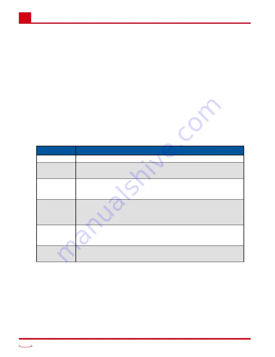
Table 6.2 Command Error Bits
Bit 7:
RPM Clamped.
This bit is set when one of the calculated advances exceeds one machine cycle.
Bit 6:
Output Forced.
This bit is set to ‘1’ if any of the outputs have been either forced on or off. Use
words 1 and 2 of the Data Attribute Block 0 to determine which outputs have been forced.
Bits 4-0:
Data Attribute Block Number.
The number of the Data Attribute Block presently being transmit-
ted by the ANS1.
Error Bits
Programming Error
0000
No errors
1000
Command Word Error.
This error will be cleared when the next correct Command Word is transmitted
to the ANS1.
1001
Parameter Error
One of the parameters in the last Command Block was outside of its defined
range. This error requires that the Clear Error command bit be used to clear
this error.
1010
Reserved Bits Error
One or more reserved bit in the Command Block were set to ‘1’. All reserved
bits must equal ‘0’. This error requires that the Clear Error command bit be used
to clear this error.
1011
Parameter Conflict Error
Two parameters, or their associated “Apply Word” bits in the command word,
are set in such a way that the programming command cannot be accepted. This
error requires that the Clear Error command bit be used to clear this error.
1100
Setpoint Overlap Error
The ranges defined by multiple setpoint pairs on an output cannot overlap. This
error requires that the Clear Error command bit be used to clear this error.
Summary of Contents for ANS1 ANYNET-I/O
Page 1: ...MICRO CONTROLS INC ADVANCED U s e r M anual Manual 940 0A090...
Page 6: ...Table of Contents ADVANCED MICRO CONTROLS INC 6 Notes...
Page 26: ...Limit Switch Functionality ADVANCED MICRO CONTROLS INC 2 26 Notes...
Page 36: ...Additional Functionality ADVANCED MICRO CONTROLS INC 3 36 Notes...
Page 90: ...LEADERS IN ADVANCED CONTROL PRODUCTS ADVANCED MICRO CONTROLS INC...


