background image


Version 1.0  


©Copyright 2017, Ambient LLC. All Rights Reserved. 


Page 5 

2.4 Display Console Set Up 

1.


Move  the  remote  thermo-hygrometer(s)  about  5  to  10’  away  from  the  display  console  (if  the 

sensor is too close, it may not be received by the display console). If you have more than one 
thermo-hygrometer,  make  sure  they  are  all  powered  up  and  transmitting  on  different 
channels.


2.


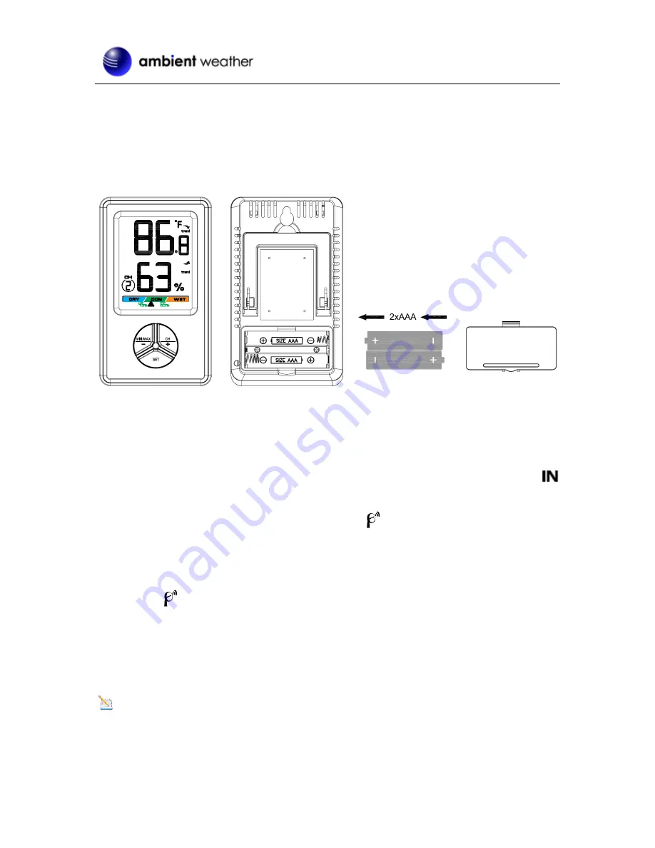
Remove  the  battery  door  on  the  back  of  the  display,  as  shown  in 

Figure  4

.  Insert  two  AAA 

(alkaline or lithium, avoid rechargeable) batteries in the back of the display console. 


Figure 4 

All of the LCD segments will light up for a few seconds to verify all segments are operating properly. 
 

3.


Replace  the  battery  door,  and  fold  out  the  desk  stand  and  place  the  console  in  the  upright 

position. 


The console will instantly display indoor temperature and humidity as designated by the 


icon.    The remote temperature and humidity will update on the display within a few minutes 
on the appropriate channel. 


While in the search mode, the remote search icon 

  will be constantly displayed.


If you have more than one remote sensor (up to eight remotes are supported), the display will 
automatically toggle between sensors until all sensors have reported in.


Do  not  touch  any  buttons  until  the  remote  sensor  has  reported  in,  or  the  transmitter  search 

icon 

  is no longer on, otherwise the remote sensor search mode will be terminated. When 

the  remote  sensor  temperature  and  humidity  has  been  received,  the  console  will 
automatically switch to the normal mode, and all further settings can be performed. 

 
              If the remote does not update, please reference the troubleshooting guide in Section 8. 

2.4.1


Display Console Layout 

Note: 

The  following  illustration  shows  the  full  segments  of  the  LCD  for  description  purposes 

only and will not appear like this during normal operation. 

Summary of Contents for WS-0416

Page 1: ...tdoor Channel Selection 8 5 5 Temperature Units of Measure 8 5 6 Sensor Search Mode 8 5 7 Best Practices for Wireless Communication 9 5 8 Adjustment or Calibration 10 5 8 1 Humidity Calibration 10 5 8 2 Temperature Calibration 11 6 Glossary of Terms 11 7 Specifications 11 7 1 Wireless Specifications 11 7 2 Measurement Specifications 12 7 3 Power Consumption 12 8 Troubleshooting Guide 13 9 Accessor...

Page 2: ...HxW 4 3 x 2 5 x 0 65 LCD Dimensions LxW 2 1 x 1 7 LCD Segment Height 0 8 inches 1 Thermo hygrometer transmitter F007TH Dimensions LxHxW 4 5 x 2 0 x 0 75 1 User Manual 2 2 Recommend Tools Hammer and nail for hanging remote thermo hygrometer transmitter 2 3 Thermo Hygrometer Sensor Set Up Note Do not use rechargeable batteries We recommend fresh alkaline batteries for outdoor temperature ranges betw...

Page 3: ...he inside cover of the lid of the transmitter Figure 2 displays all four switches in the OFF position factory default setting Figure 2 3 Channel Number The WS0416 supports up to eight transmitters To set each channel number the default is Channel 1 change Dip Switches 1 2 and 3 as referenced in Table 1 4 Temperature Units of Measure To change the transmitter display units of measure F vs C change ...

Page 4: ...g the batteries the remote sensor LED indicator will light for 4 seconds and then flash once per 60 seconds thereafter Each time it flashes the sensor is transmitting data 7 Verify the correct channel number CH and temperature units of measure F vs C are on the display as shown in Figure 3 Figure 3 1 temperature 2 temperature units F vs C 3 channel number 4 relative humidity 8 Close the battery do...

Page 5: ...rature and humidity as designated by the icon The remote temperature and humidity will update on the display within a few minutes on the appropriate channel While in the search mode the remote search icon will be constantly displayed If you have more than one remote sensor up to eight remotes are supported the display will automatically toggle between sensors until all sensors have reported in Do ...

Page 6: ...14 Min Max Record mode 15 Indoor Icon 2 4 2 Sensor Operation Verification Verify the indoor and outdoor humidity match closely with the console and sensor array in the same location about 5 to 10 apart The sensors should be within 10 the accuracy is 5 Allow about 30 minutes for both sensors to stabilize The humidity can be adjusted or calibrated later to match each other a known source Verify the ...

Page 7: ...splay Features 4 1 Comfort Icon The comfort icon is based on humidity ranges specified in Figure 7 The icon is displayed for indoor humidity remote channel 1 humidity and optional remote channels 2 8 RH 45 RH 45 65 RH 65 Dry Comfortable Wet Figure 7 4 2 Rate of Change Icon The rate of change icon detects rapid changes in temperature and humidity If the arrow points upward the temperature is increa...

Page 8: ...5 2 Clearing Min Max Daily The minimum and maximum can be set to clear daily every 24 hours automatically or manually Press and hold the SET button for 3 seconds to switch between and Clears Manually When you manually clear the minimum and maximum the Clears Daily function will clear every 24 hours from the time you clear it For example if you clear the min and max at 4 00pm it will continue to cl...

Page 9: ...ices for trouble free wireless communication 1 Electro Magnetic Interference EMI Keep the console several feet away from computer monitors and TVs 2 Radio Frequency Interference RFI If you have other 433 MHz devices and communication is intermittent try turning off these other devices for troubleshooting purposes You may need to relocate the transmitters or receivers to avoid intermittent communic...

Page 10: ... to select the humidity sensor you wish to adjust To enter the humidity calibration mode press and hold the SET and MIN MAX buttons at the same time for 5 seconds and the humidity value will begin flashing Press the CH button to increase the humidity and the MIN MAX button to decrease the humidity reading in 1 increments To rapidly increase or decrease the humidity reading press and hold the CH or...

Page 11: ...alibrate temperature we recommend a mercury or red spirit fluid thermometer Bi metal dial and other digital thermometers are not a good source and have their own margin of error Using a local weather station in your area is also a poor source due to changes in location timing airport weather stations are only updated once per hour and possible calibration errors many official weather stations are ...

Page 12: ...0 to 90 1 Outdoor Humidity 10 to 99 5 only guaranteed between 20 to 90 1 7 3 Power Consumption Base station display console 2 x AAA 1 5V Alkaline or Lithium batteries not included Remote sensor 2 x AAA 1 5V Alkaline or Lithium batteries not included Battery life Minimum 12 months for base station with one sensor and excellent reception Intermittent reception Backlight often light and multiple sens...

Page 13: ...range is 300 and 100 under most conditions Move the sensor assembly closer to the display console If the sensor assembly is too close less than 5 move the sensor assembly away from the display console Make sure the remote sensor LCD display is working and the transmitter light is flashing once per 60 seconds Install a fresh set of batteries in the remote thermo hygrometer For cold weather environm...

Page 14: ...her F007TH Wireless Thermo Hygrometer for WS0416 Weather Stations Add additional remote thermo hygrometers Supports up to eight remote sensors Ambient Weather WS0416 C WS0416 Big Digit 8 Channel Wireless Thermo Hygrometer Console Only Add as many display consoles as you like to your existing system to display the remote sensor in different locations Ambient Weather SRS100LX Temperature and Humidit...

Page 15: ...ent has been tested and found to comply with the limits for a Class B digital device pursuant to Part 15 of the FCC Rules These limits are designed to provide reasonable protection against harmful interference in a residential installation This equipment generates uses and can radiate radio frequency energy and if not installed and used in accordance with the instructions may cause harmful interfe...

Page 16: ...er s manual 3 damage resulting from the performance of repairs or alterations by someone other than an authorized Ambient LLC authorized service center 4 units used for other than home use 5 applications and uses that this product was not intended 6 the products inability to receive a signal due to any source of interference or metal obstructions and 7 extreme acts of nature such as lightning stri...

Reviews: