Cleaning, maintenance and repair
Replacing the piston diaphragm
•
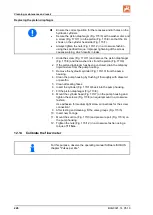
Ensure the correct position for the recesses and/or holes on the
hydraulic cylinders.
•
Secure the piston diaphragm (Fig. 173/8) with a washer disc and
a screw (Fig. 173/11) on the piston (Fig. 173/9), so that the rim
shows on the cylinder head side (Fig. 173/7).
•
Always tighten the nuts (Fig. 173/1,2) in a crosswise fashion
using the specified torque. Improper tightening of the screws
causes warping, which results in leaks.
1. Undo the screw (Fig. 173/11) and remove the piston diaphragm
(Fig. 173/8) and the washer disc from the piston (Fig. 173/9).
2. If the piston diaphragm has been punctured, drain the oil/spray
liquid mixture from the pump housing.
3. Remove the hydraulic cylinder (Fig. 173/10) from the pump
housing.
4. Clean the pump housing by flushing it thoroughly with diesel oil
or paraffin.
5. Clean all sealing faces.
6. Insert the cylinder (Fig. 173/10) back into the pump housing.
7. Fit the piston diaphragm (Fig. 173/8).
8. Mount the cylinder head (Fig. 173/7) on the pump housing and
tighten the screws (Fig. 173/6) an equal amount in a crosswise
fashion.
Use adhesive for medium tight screw connections for the screw
connection!
9. After testing and cleaning, fit the valve groups (Fig. 173/5).
10. Insert new O-rings.
11. Mount the suction (Fig. 173/3) and pressure port (Fig. 173/4) on
the pump housing.
12. Tighten the nuts (Fig. 173/1,2) in a crosswise fashion using a
torque of
11 Nm
.
12.14
Calibrate the flow meter
For this purpose, observe the operating manual Software ISOBUS
chapter "Pulses per litre".
226
BAG0021.14 05.19
Summary of Contents for UG 2200 Special
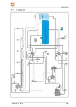
Page 237: ...Liquid circuit 13 1 UG Special BAG0021 14 05 19 237 ...
Page 238: ...Liquid circuit 13 2 UG Super 238 BAG0021 14 05 19 ...
Page 242: ...Spray table Fig 182 242 BAG0021 14 05 19 ...
Page 251: ...Spray table BAG0021 14 05 19 251 ...
Page 252: ......


