RS1200004 Rev. 0
18
Refrigerant Flow
18, 21, 22 cu. ft. Bottom Mount
Refrigerant Flow Diagram
SuctionTube
ProcessTube
Drier
Subcooler
Condenser
Compressor
DIscharge
Tube
Evaporator
CapillaryTube
Page 1: ...onsibility for property damage or personal injury for improper service procedures done by an RS1200004 Revision 0 May 2001 18 21 22 Cu Ft Bottom Mount Refrigerators This Base Manual covers 18 21 and 22 Cu Ft Bottom Mount Refrigerators Refer to individual Technical Sheet for specific information on models ...
Page 2: ...e from improper service procedures If performing service on your own product assume responsibility for any personal injury or property damage which may result To locate an authorized servicer please consult your telephone book or the dealer from whom you purchased this product For further assistance please contact CONSUMER AFFAIRS DEPT OR 1 319 622 5511 or 1 800 843 0304 AMANA APPLIANCES CALL and ...
Page 3: ... Refrigerant Flow 18 21 22 cu ft 18 Cabinet Air Flow 21 22 cu ft 19 18 cu ft Cabinet Air Flow Diagram 20 Machine Compartment Air Flow Diagram 21 Typical External Sweat Pattern 22 Troubleshooting Chart 23 System Diagnosis 26 Disassembly Procedures Doors 29 Refrigerator Compartment Light bulb light switch 29 Temp Assure Damper control 29 Freezer Compartment Freezer Temperature Control 30 Light Switc...
Page 4: ...ers compressor To raise temperature of gas suction line is placed in heat exchange with capillary Temperature Controls Freezer compartment temperature is regulated by air sensing thermostat at top front of freezer compartment which actuates compressor Control capillary is inserted in well which routes capillary into freezer Control should be set to maintain freezer temperature between 0 to 2 F Fre...
Page 5: ...onnect power to refrigerator 2 Discharge capacitor if present by shorting terminals through a resistor 3 Remove compressor leads and use an ohmmeter set on highest scale 4 Touch one lead to compressor body clean point of contact and other probe to each compressor terminal If reading is obtained compressor is grounded and must be replaced Operation test If voltage capacitor overload and motor windi...
Page 6: ...is very important that adequate air flow over condenser is maintained Condenser is air cooled by condenser fan motor If efficiency of heat transfer from condenser to surrounding air is impaired condensing temperature becomes higher High liquid temperature means liquid will not remove as much heat during boiling in evaporator as under normal conditions This would be indicated by high than normal he...
Page 7: ...pening by disconnecting electrical leads to control and turning control knob to coldest setting Check for continuity across terminals Altitude Counter in Feet Feet Above Sea Level Turn Screw Clockwise Angular Degrees Control freezer temperature Altitude Adjustment When altitude adjustment is required on a G E control turn altitude adjustment screw 1 7 turn counter clockwise for each 1 000 feet inc...
Page 8: ...ber B2150504 Before opening refrigeration system recover HFC134a refrigerant for safe disposal 1 Cut drier out of system using the following procedure Do not unbraze drier 2 Applying heat to remove drier will drive moisture into the system 3 Score capillary tube close to drier and break 4 Reform inlet tube to drier allowing enough space for large tube cutter 5 Cut circumference of drier 1 below co...
Page 9: ...to defrost mode Wattmeter should read specified watts according to Technical Data Sheet 3 When defrost thermostat reaches specified temperature 5 F see Technical Data Sheet thermostat should interrupt power to heater Thermostat Thermostat is in a series circuit with terminal 2 of defrost timer and defrost heater Circuit is complete if evaporator fan motor operates when cold Controls the circuit fr...
Page 10: ...il system Equipment must be exclusively used for HFC134a Exclusive use of equipment only applies to italic items Evacuation pump Check with vacuum pump supplier to verify equipment is compatible for HFC134a Robinair Model 15600 2 stage 6 cubic feet per minute pump is recommended Four way manifold gauge set with low loss hoses Leak detector Charging cylinder Line piercing saddle valve Schroeder val...
Page 11: ...ead on test cord attaches to M terminal on compressor Service Procedures C R S Fuses Capacitor Compressor Switch To AC supply Attaching Capacitor for Compressor Test 5 Connect a known good capacitor into circuit as shown above For proper capacitor size and rating see technical data sheet for unit under test NOTE Ensure test cord cables and fuses meet specifications for unit under test see Technica...
Page 12: ...leaks are best detected with halide or electronic leak detectors Testing Systems Containing a Refrigerant Charge 1 Stop unit operation turn refrigerator off 2 Holding leak detector exploring tube as close to system tubing as possible check all piping joints and fittings NOTE Use soap suds on areas leak detector cannot reach or reliably test Testing Systems Containing No Refrigerant Charge 1 Connec...
Page 13: ...ressure and wattage while low side is being pumped out Testing for Restrictions To determine if a restriction exists 1 Attach gauge and manifold between suction and discharge sides of sealed system 2 Turn unit on and allow pressure on each side to stabilize Inspect condenser side of system Tubing on condenser should be warm and temperature should be equal throughout no sudden drops at any point al...
Page 14: ... all other valves and start vacuum pump Vacuum Pump 6 cm Copper Tubing Compressor Compressor Process Tube Charging Hose Thermistor Vacuum Gauge Low Side Gauge E Valve B D Valve High Side Gauge Charging Hose Drier Process Tube F Valve Charging Cylinder C A Equipment Setup For Evacuation And Charging 5 After compound gauge low side drops to approximately 29 inches gauge open valve C to vacuum thermo...
Page 15: ...Start compressor and draw remaining refrigerant from charging hoses and manifold into compressor through compressor process tube 6 To check high side pinch off drier process tube Close valve D to high side gauge If high side pressure rises repeat high side pinch off and open valve D Repeat until high side pinch off does not leak 7 Pinch off compressor process tube and remove charging hose Braze st...
Page 16: ...formation HFC134a is alternative refrigerant for CFC12 HFC134a has an ozone depletion potential ODP factor of 0 0 and a global warming potential GWP factor of 0 27 HFC134a is not flammable and has acceptable toxicity levels HFC134a is not interchangeable with CFC12 There are significant differences between HFC134a and CFC12 which must be considered when handling and processing refrigeration system...
Page 17: ...minutes after thermocouples are installed Turn control to colder to obtain required on time Wattage reading must be recorded in conjunction with temperature test to confirm proper operation Suction and head pressures are listed on Temperature and Relationship Chart Normally these are not required for diagnosis but used for confirmation on systems which have been opened Service Procedures To avoid ...
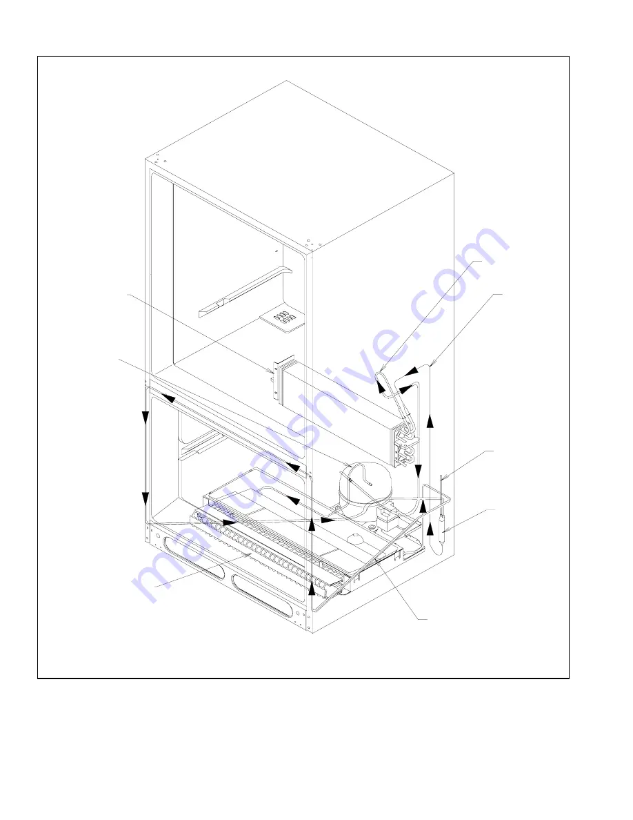
Page 18: ...RS1200004 Rev 0 18 Refrigerant Flow 18 21 22 cu ft Bottom Mount Refrigerant Flow Diagram Suction Tube Process Tube Drier Subcooler Condenser Compressor DIscharge Tube Evaporator Capillary Tube ...
Page 19: ...ir Flow Diagram Evaporator Evaporator Fan Assembly Refrigerator Air Supply Tunnel To Fresh Food Compartment Control Damper Deli Drawer Air Supply Ports some models Refrigerator Return Air Duct Freezer Air Supply Grille Freezer Return Air Through Bottom of Evaporator Cover ...
Page 20: ...t Cabinet Air Flow Diagram Freezer Return Air Through Bottom of Evaporator Cover Evaporator Evaporator Fan Assembly Freezer Supply Grille Refrigerator Return Air Tunnels Refrigerator Air Supply Tunnel To Fresh Food Compartment Control Damper Evaporator Cover ...
Page 21: ...21 RS1200004 Rev 0 18 21 22 cu ft Model Bottom Mount Machine Compartment Air Flow Diagram Machine Compartment Air Flow Condenser Compressor Condenser Fan Assembly Drip Pan ...
Page 22: ...r mullion Freezer door top Freezer door bottom Lower mullion 1 CLASSIFICATION OF CONDENSATION 1 Haze or fog 2 Beading 3 Beads or small drops 4 Drops running together No sweat on side when compressor is running Conditions after 4 hour Laboratory Sweat Test Ambient 90 dF Relative humidity 84 Refrigerator Temp 40 dF Freezer Temp 0 dF ...
Page 23: ...cessive door opening Consumer education Overloading of shelves Consumer education Warm or hot foods placed in cabinet Consumer education Cold control set too warm Set control to colder setting Poor door seal Level cabinet Adjust hinges Replace gasket Refrigerator airflow Check damper is opening by removing grille With door open damper should open Replace if faulty Turn control knob to colder posit...
Page 24: ...tion Repair evacuate and recharge system Refrigerant overcharge Check for overcharge Evacuate and recharge system Unit runs continuously Air in system Check for low side leak Repair evacuate and recharge system Unit runs continuously Temperature normal Ice on evaporator See Ice on evaporator Unit runs continuously Temperature too cold Faulty defrost thermostat Check thermostat Replace if necessary...
Page 25: ...eck overload protector for continuity If open replace overload NOTE Ensure overload compressor are below trip temperature before testing Faulty compressor motor capacitor some compressors do not require motor capacitor Check capacitor for open short Replace if necessary NOTE Discharge capacitor before testing Faulty fan motor Check fan motor Replace if failed Restricted air flow Check condenser an...
Page 26: ...re of the defrost system the refrigerant will flood out and cause the suction line to frost or sweat The cause of this problem should be corrected rather than to purge refrigerant from the sytem Running the freezer section colder than necessary 2 to 1 F is considered normal package temperatures or continuous running of the compressor for a variety of reasons or the freezer fan motor not running ma...
Page 27: ...stem replace the drier filter evacuate and recharge with the specified refrigerant charge If the unit performs normally three possibilities exist 1 refrigerant loss 2 partially restricted drier filter and 3 moisture in system If the unit performs as it previously did you may have a restricted capillary line or condenser or kinked line Find the point of restriction and correct it A restriction redu...
Page 28: ... temperature raises Refrigerators installed in ambient temperatures lower than 60 F will not perform as well because the pressures within the system are generally reduced and unbalanced This means that the lower head pressure forces less liquid refrigerant through the capillary line The result is the symptoms of a refrigerant shortage The lower the ambient temperature the more pronounced this cond...
Page 29: ...and or property damage make sure unit doors are taped shut before you undertake the next steps 3 On top of unit remove and retain plastic cap from door hinge 4 Remove and retain screws from top door hinge Unless door reversal is intended leave Posi Pin shim in place 5 Pull tape off of door and lift door off unit Set door on a padded surface to prevent damage to finish 6 Remove and retain center hi...
Page 30: ...ction cover Remove mounting screw and cover 2 Near icemaker connections in left side of freezer compartment two plastic buttons cover holes for mounting icemaker Loosen screws that hold buttons in place Remove screws and buttons 3 Loosen and remove screws that hold 2 shelf glides in place at left and right sides of compartment 4 Pull front end of each glide away from the wall and in toward center ...
Page 31: ...ondensate drip pan may spill when steps 1 thru 4 are performed Have a towel ready to mop up spillage 1 Raise back of refrigerator at least 4 off the deck and block it up 2 Remove condenser fan grille heat exchanger cover and machine compartment cover 3 Remove two rear mounting bolts from compressor 4 With a Torx driver remove mounting screws from both ends of cabinet brace 5 Remove rollers from ca...
Page 32: ...eat exchanger cover machine compartment cover and condenser fan grille 2 Remove drier 3 Disconnect all compressor wiring 4 Unbraze low and high pressure lines at compressor 5 Remove compressor mounting bolts 6 Lift compressor out of unit NOTE Install new drier and compressor per instructions in Service Procedures Evacuate and recharge sealed system per instructions in Service Procedures Condenser ...
Page 33: ...A 1 RS1200004 Rev 0 Appendix A ...
Page 34: ...N M H T L V Specifications Mold Heater 185 Watts 264 Ohms Thermostat Close 8 1 C 17 3 F Bimetal Opens 0 1 C 17 3 F Water Fill 140 cc 7 5 Sec Motor Cycle Stamped in Circuit Plug in Connectors One Revolution of blades take three minutes plug stall time on ice Eject and Water Fill Testing Procedures Ice maker plugged into power shut off arm down freezer cold 1 Test point L and N will verify 230 volts...
Page 35: ... Note knob position and reinstall in same position for same water fill To avoid possible electrical shock always turn off power before beginning any disassembly Module Motor and Support Assembly Insert phillips driver in access ports in module Loosen both screws Disconnect shut off arm Pull mold from support assembly To remove module only remove three phillips screws and pull module out of housing...
Page 36: ...tor is defective it will run The shut off arm must be in the on position NOTE There are several slotted shafts on the motor assembly board Do not under any circum stances insert a screwdriver and attempt to turn these shafts The slots are to permit as sembly only NOTE There are not repairable or replaceable components in the module Unless you are replacing the module there should be no need to rem...
Page 37: ...stes and sediment filter Part Number R0183114 Mineral contact can also lime up the mold causing wicking of water over the mold and poor cube release Silicone is applied at the upper edges around fill cup and stripper Temperature Problems Temperatures in freezer section which average above the normal 18 1 C 0 2 F will slow production of ice Complaints of inadequate ice cube production may be correc...
Page 38: ...f wa ter allowed to enter ice maker mold is directly propor tional to the length of time the water valve switch is held closed by the timing cam Inside the valve is a flow washer which acts as a water pressure regulator Proper ice maker fill is 140 cc 10 cc at 7 5 seconds of water fill at an inlet pressure ranging from 1 4 to 8 2 bar 20 to 120 PSI When the light blue encapsulated solenoid is ener ...
Page 39: ...ter Pressure NOTE Jump Cycle through T H Probe holes for 10 Sec Then Remove Jumpers Catch Water in Glass f Water Pressure Must Be Increased 20 120 psi 1 4 8 2 bar Should be About 140 cc s g Open Heater Circuit g Change Mold and Heater Assembly h Closed Thermostat h Change Thermostat i Damaged Heater Tulips on Module i Change Module j Heater Pins Too Short Not Contacting Module j Change Mold Heater...
Page 40: ...Oscillating 3 Change Mold Heater Assy Apply Fresh Coat Of Alumilastic 4 Little No Alumilastic on Thermostat 4 Apply Fresh Coat Of Alumilastic 5 Heater Not Staked In Mold 5 Change Mold Heater Assy Apply Fresh Coat Of Alumilastic 6 Broken Locking Tabs on Vertical Cam 6 Change Module D 6 00 Ejector Position 1 Contamination 1 Change Ice Maker Module 2 Hollow Cubes 2 Refer to Section III Hollow Cubes 3...
Page 41: ... Apply Fresh Alumilastic 2 Jammed Cube Stalled In Water Fill Cycle 2 Remove Cube Determine Reason For Stall 3 Leaky Water Valve 3 Change Water Valve 4 Fill Volume of Water Valve Excessive 4 Change Water Valve 5 Motor Stalled In Water Fill Cycle 12 00 Ejector Position 5 Change Ice Maker Module 6 Contaminated Module 6 Change Ice Maker Module 7 Refrigerator or Ice Maker Not Level 7 Level As Necessary...
Page 42: ...RS120004 Rev 0 A 10 Ice Maker Wiring Diagram and Parts Layout 230 ...
Page 43: ...B 1 RS1200004 Rev 0 Appendix B ...
Page 44: ...allet To avoid property damage don t leave unit lying on its back any longer than is absolutely necessary CAUTION 6 Lift refrigerator back into upright position Remove and discard cardboard from between doors To avoid risk of electrical shock that can cause death or severe personal injury disconnect unit from power before removing doors Connect to power only after doors are replaced WARNING Remove...
Page 45: ...enclature C Remove bottom hinge pin and all shims from bottom hinge bracket Note number of shims Retain all parts D With 3 8 nut driver loosen 3 mounting screws from bottom hinge bracket Remove and retain bracket and screws Situate the unit 1 Wrap refrigerator carefully with blanket or appliance pad Slide appliance cart under side of unit Thread cart strap around refrigerator and tighten strap 2 M...
Page 46: ...e of freezer door handle trim cap Use a flat tipped screwdriver in those notches to pry up and remove trim cap 6 Removal of trim cap exposes two Phillips head screws With a No 2 Phillips screwdriver remove those screws and remove freezer door handle 7 From top edge of freezer door at the hinge side remove two button plugs Transfer plugs to opposite side of door Use plugs to fill holes left vacant ...
Page 47: ...ge pin with all shims NOTE On any unit button plug should be in hole at inside edge of bottom hinge bracket Hinge pin with shims should be in hole at outer edge of bracket 18 On bottom edge of both refrigerator and freezer doors use a No 2 Phillips screwdriver to move door stops to sides opposite their present location Toe grille Bottom hinge cap Brake foot Bottom hinge bracket Button plug Bottom ...
Page 48: ...t driver some units require a 9 32 nut driver to remove the center hinge pin Note location of all shims above or below hinge Retain all parts for use in reassembly 6 Lift freezer door off bottom hinge and set door aside on a clean padded surface to protect the finish and customer s property Verify that all shims stay with bottom hinge pin 7 Remove toe grille and bottom hinge cap s 8 From the cente...
Page 49: ...door skin End cap End cap End cap End cap Refrigerator door Freezer door Refrigerator door handle Freezer door handle Button plug Button plug Screws Screws Screws Contour Door Nomenclature Handle clips Handle clips Handle clips Installation Instructions ...
Page 50: ...refrigerator door on a protected surface carpeted floor or table covered with blanket 13 Remove end caps Remove screws from cap on each end of door Move button plug to hole at opposite side of door 14 Remove refrigerator door handle Use rubber mallet to tap underside of handle toward top end of door Handle will slide upward approximately 1 2 and release from handle clips Remove handle clips Retain...
Page 51: ...owels ready to soak up spillage before attempting the rest of these steps b Confirm that water pressure at refrigerator end of water supply line is between 20 psi and 100 psi between 1 4 and 7 0 kg cm2 NOTE Units with filter require pressure between 35 psi and 100 psi 2 5 and 7 0 kg cm2 NOTE Water valve in your refrigerator will not work properly if system pressure is not within spec c Remove plas...
Page 52: ... instructions in the owner s manual 4 Align refrigerator door a Lay a carpenter s level across front edge of unit b At bottom of unit in front Turn roller adjustment screws and or use shims as needed to raise or lower corners until unit is level and stable Rear roller adjustment screw Front roller Bottom hinge bracket b At top of unit side opposite hinges refrigerator door corner should be about 1...
Page 53: ...C 1 RS1200004 Rev 0 Appendix C ...
Page 54: ...ture reference Be sure this manual stays with refrigerator As an Energy Star Partner Amana has determined that this product meets the Energy Star guidelines for energy efficiency Energy Star applies to some models Qualifying models are designated with the Energy Star logo located on the product ...
Page 55: ... Please read this Owner s Manual thoroughly This manual provides proper maintenance information Any questions call the Consumer Affairs Department at 1 800 843 0304 inside U S A and 1 319 622 5511 outside the U S A or contact us on the internet at www amana com Complete registration card and promptly return If registration card is missing call the Consumer Affairs Department When contacting Amana ...
Page 56: ... ofYour Refrigerator IMPORTANT Child entrapment and suffocation are not problems of the past Junked or abandoned refrigerators are still dangerous even if they will sit for just a few days If you discard an old refrigerator please follow the instructions below to help prevent accidents BEFORE YOU THROW AWAY YOUR OLD REFRIGERATOR OR FREEZER Take off the doors Leave the shelves in place so that chil...
Page 57: ...t A B Reverse Handles side mounted design To reverse handles on contour model see service notice at top of page 2 Remove 1 plug from top hinge side of door and 2 from front hinge side of door Replace 3 plugs in empty mounting holes 3 Mount refrigerator handle on opposite side of door using mounting screws removed in previous step 4 Snap handle trim into place and replace screw at top of handle A B...
Page 58: ... Do not install copper tubing in area where temperatures drop below 32 F 0 C Materials Required O D 6 mm flexible copper tubing open end wrench Length of copper tubing must reach from water supply connection to water valve inlet port on back of refrigerator plus additional 8 ft 2 m of tubing for a service loop A service loop will allow refrigerator to be pulled away from the wall without disconnec...
Page 59: ... roller adjustment screws to raise or lower refrigerator cabinet Front of refrigerator must be 6 mm or bubble on your level higher than the back of your refrigerator Make sure refrigerator cabinet is level from side to side by adjusting left and right roller adjustment screw A Turn stabilizing leg C some models clockwise until firmly against floor 4 Replace toe grille D and bottom hinge cover B Se...
Page 60: ...ce Maker Water supply to refrigerator is turned on Water leaks are not present at connection between household water supply and refrigerator After 24 hours consumer should check connection for water leaks Ice maker arm is in on position for ice production It may take up to 24 hours for first harvest of ice Product Literature Owner s manual is reviewed including the following information product re...
Page 61: ... is coldest Set controls precisely using a household thermometer with a temperature range between 5 to 50 F 21 to 10 C Put thermometer snugly between frozen packages in freezer section Wait 5 8 hours If Deepfreeze temperature is not 0 to 2 F 17 to 16 C adjust Deepfreeze control one number at a time Check again after 5 8 hours Put thermometer in a glass of water in middle of Fresh Food section Wait...
Page 62: ...rature Chiller FreshTM control is located below front shelf trim Control adjusts amount of air circulating around drawer Slide control to COLD for normal refrigerator temperature and to COLDER for colder temperature Ice crystals may form on drawer or food on COLDER setting Cold air entering the Chiller FreshTM drawer can decrease refrigerator temperature Fresh Food control may need to be adjusted ...
Page 63: ...torage for butter cheese etc Remove dairy center by lifting door pushing tabs of shelf down on both sides and pulling out Replace dairy center by sliding in until tabs lock into place then lower door A B A Door B Tab 5 Replace shelf by inserting hooks into metal track and lowering the front Use slots 4 though 6 only 6 Replace drawer by sliding in Make sure boot fits snugly over air inlet in back w...
Page 64: ...tainer fits on front edge of any refrigerator door bucket or door shelf A A Tabs Door Shelves Remove door shelves by lifting ends and pulling out Replace door shelves by placing shelf on glides and sliding down A A Glide Adjustable Divider some models Adjustable divider keeps items in place and adjusts to meet individual storage needs Divider fits in any door bucket or door shelf Bottle Holder som...
Page 65: ...ng is automatic under normal conditions Automatic Ice Maker some models Make sure ice bucket is in place and ice maker arm is down B A C A Off position C On position B Ice maker arm After freezer section reaches normal temperature the ice maker fills with water and begins operating For optimum ice production it is recommended that freezer section be at least half full Allow 24 48 hours after insta...
Page 66: ...bin Vertical Basket Divider Install vertical basket divider by completing the following steps 1 Align clips on side of divider with rungs in basket wall 2 Press top of divider down until divider meets bottom of basket To remove divider 1 Grasp top of divider and pull straight up A A Vertical basket divider Tilt Out Bin some models The tilt out bin provides convenient storage for frozen food items ...
Page 67: ...nd Cleaning WARNING Disconnect power to refrigerator before cleaning to avoid electrical shock which can cause severe personal injury or death After cleaning restore power CAUTION Read and follow all manufacturer s cleaning directions to avoid personal injury or property damage General See section on Stainless Steel Cleaning if doors are stainless steel 1 Wash surfaces with 4 tablespoons baking so...
Page 68: ...n replacing light bulb Fresh Food Light Remove light bulb cover by removing hex nut screws Replace with appliance bulb no greater than 60 watts Replace light bulb cover by replacing hex nut screws A B A hex nut screws B Light bulb cover Vacation Tips Complete the following steps for short vacations 1 Remove perishable foods 2 If an ice maker is installed move ice maker arm to Off position See Auto...
Page 69: ... sizzles hisses or pops 5 Defrost timer sounds like an electric clock and snaps in and out of defrost cycle 6 Condenser fan air rushes and whirs 7 Compressor has a high pitched hum or pulsating sound and cycles on and off 8 Ice cubes from ice maker some models drop into ice bucket 9 Ice maker water valve hookup some models buzzes when ice maker fills with water This occurs whether or not refrigera...
Page 70: ...ks vents or restricts airflow Chiller Fresh System temperature is too warm Slide control to colder setting Adjust freezer control to colder setting See Setting Controls instructions of Controls section Verify Chiller Fresh System cap has been moved if drawer has been moved from left to right side of cabinet See Chiller Fresh System section Food temperature is too cold Clean condenser coil See Cond...
Page 71: ...ker requires a water pressure of 20 100 psi to function properly Confirm ice maker arm is down See Automatic Ice Maker section Confirm household water supply is reaching water valve Make sure the water valve shut off is fully turned on Piercing type or 3 16 saddle valve was used for hookup Both reduce water flow and may become clogged with time Replace these valves with correct type of saddle valv...
Page 72: ...ociation listing when shipped from the factory Service must be performed by an authorized Amanatechnician Warranty IsVoid If Serial plate is defaced Product is used on a commercial rental or leased basis Product has defect or damage due to product accident alteration connection to an improper electrical supply fire flood lightning or other conditions beyond the control of Amana Appliances Product ...