


unable to correct (e.g. errors caused by changes in the process load). When the integral gain is
correctly adjusted the control output is varied to maintain control by keeping the process variable
at the same value as the control setpoint. Since the integral gain is time based the output will
gradually increase if the error does not decrease i.e. if the measured value remains constant and
there is an error (a difference between the measured value and the setpoint) then the frequency will
be increased compared to the previous frequency output. The higher the proportional gain, the
greater the degree by which the on to off ratio will be affected i.e. the response will be greater at
higher integral gain settings. With an integral gain of
1.000
an error of
10
or more (with control
span set at
10
) will cause the integral action to try to correct at the rate of 100% minute. With
an integral gain of
0.200
an error of
10
or more will cause the integral action to try to correct at
the rate of 20% per minute. Too high an integral gain will result in instability. To low an integral
gain will slow down the time taken to reach the setpoint. The optimum setting will depend on
the lag time of the process and the other control settings. Start with a low figure (e.g.
0.200
)
and increase until a satisfactory response time is reached. The integral gain figure has units of
gain/minute. The integral action can be reversed by setting a negative gain figure, note that the
sign of the integral gain must match the sign of the proportional gain. The integral control output
follows the formula:
Integral control output
=
error
×
Ig
×
time
(
seconds
)
60
+
previous integral control output
Where
Ig
is the integral gain set via
A
x.
IG
.
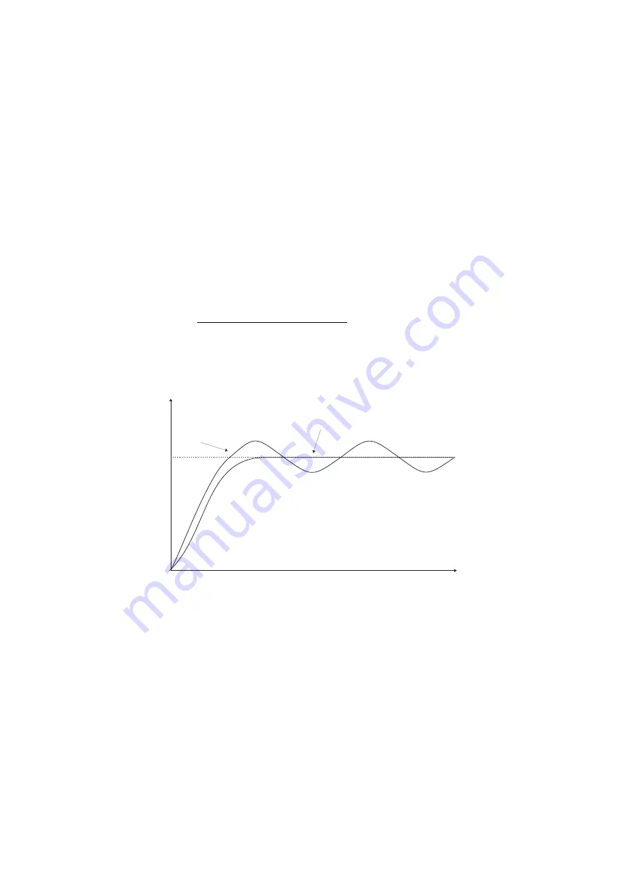
Integral gain
too high
Ideal
SETPOINT
PROCESS
TIME
7.6
PI relay integral control high limit
Display:
A
x.
IH
Range:
0.0
to
100.0
Default Value:
100.0
The maximum limit can be used to reduce overshoot of the control setpoint when the control
output is increasing i.e. rising above the setpoint. Other than this the limit operates in the same
manner as the low limit described previously.
42 of
RM4IVMAN-2.1-0
Summary of Contents for RM4-IV
Page 8: ...8 of 49 RM4IVMAN 2 1 0...
Page 10: ...10 of 49 RM4IVMAN 2 1 0...


