background image

Installation Instructions

4 / 11 / 2022 / Rev 1

1170 N Red Gum St, Anaheim, CA 92806

©  ALUZ All Rights Reserved. ALUZ reserves the right to make changes or withdraw specifi cations without prior notice.

[email protected]

aluz.lighting

866.ALUZ.LTG | 714.535.7900

A8 Series 

|


LED Tape

ZIZA


Standard

(A8-ZIZA-STN)

Page 8 of 12

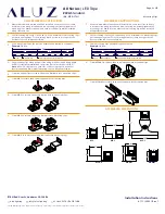
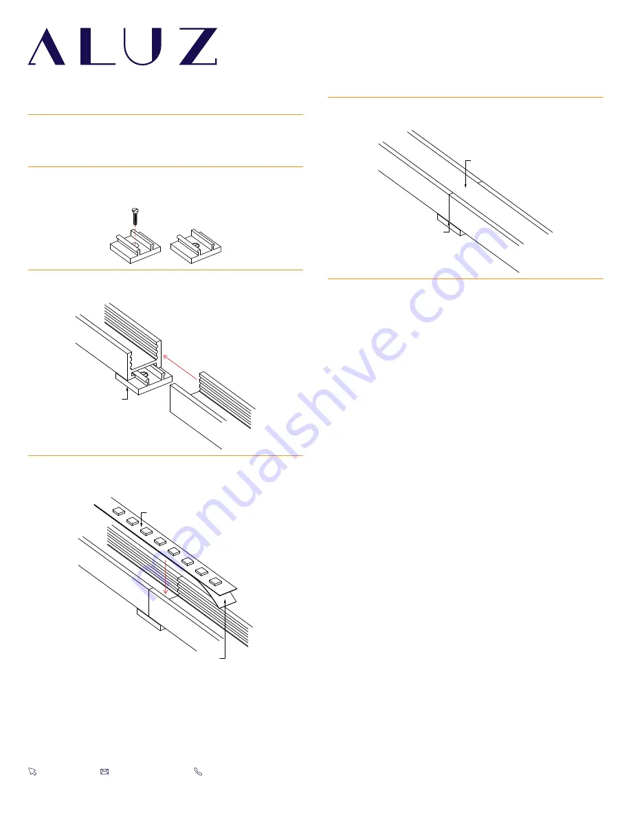
Mounting Fixture 

(Dry Location Mounting Clips)

MC

Remove adhesive backing

Install lightstrip into extrusions

Lens overlapping

Two extrusions meet

1

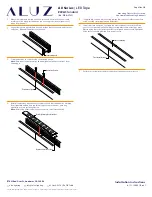
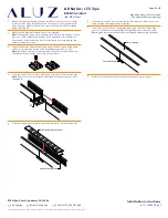
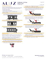
Measure area where luminaire will be installed. Use a laser line to create 

a reference line along installation area, ensuring consistent alignment of 

mounting clips. Mark location where each mounting clip will be installed 

along reference line.

6

If applicable, connect disconnects between luminaires or solder connectors 

using the steps from Application Guidelines.

3

Lay mounting clips along reference line and pre-drill using an appropriate 

drill bit for surface and screw size. Recommendation: 8/32 x 1” screw.

Note:

 Allow 0.25” clearance for lateral expansion of assembled mounting 

clips. Only install mounting clips on flat, even surfaces.

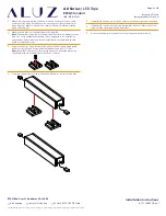
2

Mark location where mounting clips will be installed.

Note: 

The number of required mounting clips differs for dry and wet location 

products. Verify number of mounting clips is appropriate for installation 

environment before installing. Do not install luminaires with inadequate 

number of mounting clips.

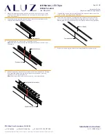
7

Install lens into extrusion, overlapping where two extrusions meet. Plan 

your cuts so that the lens will always overlap where two extrusions meet. 

Overlapping lenses helps keep extrusions aligned and prevents light leaks.

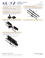
4

Screw mounting clips to surface, then snap extrusions into mounting clips.

Note:

 Ensure extrusions are aligned. Misalignment will prevent lens from 

snapping in.

8

Perform a continuity test before connecting luminaire to power source.

5

After all extrusions have been securely mounted, remove adhesive backing 

from lightstrip and adhere in place along extrusion channel, ensuring 

lightstrip is secure inside extrusion.

Note: 

Refer to Application Guidelines to ensure correct installation.

Summary of Contents for A8 Series

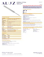
Page 1: ...W 21 4 5W Luminaire Voltage 24VDC PRODUCT INFORMATION For accent decorative surface recessed or pendant lighting 24 Volts DC for easy and safe installation Long life energy efficient LEDs Can be ordered to specific lengths for when exact dimensions are known Example 10 x 10 6 Plug and light system Lead wires are typically 36 long and exit on one end ELECTRICAL REQUIREMENTS Luminaires require a 24 Vo...

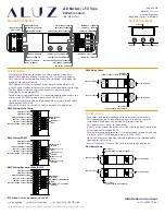
Page 2: ... feed through wires inside LED Lightstrip will void warranty Ground Fault Circuit Interrupter GFCI protections should be provided on circuits or outlets when LED Lightstrip is used for outdoor applications Surge protector must be set up for electrical power system to avoid damaging LED Lightstrip lighting system Do not connect wires together follow provided wiring diagrams Do not cut wire while en...

Page 3: ...s 001 A DMX Control System by others must be used to operate the lighting The last driver in a daisy chain sequence must be terminated Driver load not to exceed 100W For best dimming performance it is recommended to load drivers to a minimum of 50 50W and a maximum of 80 80W Up to 28 drivers may be daisy chained together using shielded cable specified for DMX wiring Ensure DIP Switch 1 is set to ON...

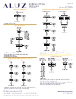
Page 4: ...FF Color SHOW 00 20 SPEED 99 99 INTENSITY 0 255 DISPLAY OFF Show Standalone Operation should only be used when a control system is not present to control the lighting not recommended DMX ADDRESS NETWORK RESOLUTION DMX TERMINATION NETWORK SETUP INTERPOLATION 1 512 8 BT 16 BT YES NO AUTO MANU OFF VID COLR WHIT GLOW DISPLAY OFF NO ADDRESS ADDRESS SET NO OF BALLASTS DISPLAY OFF Set DMX Address Set DAL...

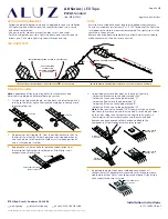
Page 5: ...ER WIRE SOLDER COVERING WIRE AND PADS WELLER 0 50 SOLDER WIRE SOLDER COVERING WIRE AND PADS COVER CONNECTIONS WITH SILICONE SOLDERING GUIDE 1 Cut lightstrip to desired length Include both sets of solder pads by cutting to the left or right of designated markings allowing more space for soldering 2 Prepare wires by stripping 1 8 from the end of each wire then tin the tips of the wire with solder Ap...

Page 6: ...line and pre drill using an appropriate drill bit for surface material and screw size Typical screw size is 8 32 x 1 Note Allow 1 4 clearance on each side of mounting clip to account for lateral expansion Only install mounting clips on flat even surfaces 3 Space mounting clips evenly throughout the run Example 20 Run 2 Use 1 mounting clip every 2 rounded up Use a minimum of 2 mounting clips per lu...

Page 7: ... disconnects between luminaires or solder connectors using the steps from Application Guidelines 3 Screw extrusions to surface using countersink screws Note Ensure extrusions are aligned Misalignment will prevent lens from snapping in 7 Perform a continuity test before connecting luminaire to power source 2 Lay extrusions along chalk line and drill at least 3 countersink holes per extrusion Drill ...

Page 8: ...n 8 32 x 1 screw Note Allow 0 25 clearance for lateral expansion of assembled mounting clips Only install mounting clips on flat even surfaces 2 Mark location where mounting clips will be installed Note The number of required mounting clips differs for dry and wet location products Verify number of mounting clips is appropriate for installation environment before installing Do not install luminair...

Page 9: ...g clips Mark location where each mounting clip will be installed along reference line 3 Lay mounting clips along reference line and pre drill using an appropriate drill bit for surface and screw size Recommendation 8 32 x 1 screw Note Allow 0 25 clearance for lateral expansion of assembled mounting clips Only install mounting clips on flat even surfaces 2 Mark location where mounting clips will be...

Page 10: ...ht leaks test before connecting luminaire to power source 7 Perform a continuity test before connecting luminaire to power source 1 Measure area where luminaire will be installed Use a laser line to create a reference line along installation area ensuring consistent alignment of mounting channels 3 Screw extrusions to surface using countersink screws Note Ensure extrusions are aligned Misalignment...

Page 11: ... 0 25 clearance for lateral expansion of assembled mounting clips Only install mounting clips on flat even surfaces 2 Mark location where mounting clips will be installed Note The number of required mounting clips differs for dry and wet location products Verify number of mounting clips is appropriate for installation environment before installing Do not install luminaires with inadequate number o...

Page 12: ...positive and negative copper pads to touch 1 Turn power off before beginning Verify power is turned off by using a non contact circuit tester Touch the probe of the tester to positive wire of the power source The tester will light up if an electrical current is detected 2 Setup your tester First insert the black probe lead into the COM jack then insert the red probe lead into the VΩ jack Metal Fla...

Reviews: