background image

14

DELTA ADVANCE     instruction manual

ENGLISH

1

 PRESENTATION AND GENERAL POINTS

1.1


GENERAL POINTS

The DELTA ADVANCE cutting machine has been designed taking into account the 

safety regulations in force in the EEC.

The safety of the personnel involved in the handling of this type of machine is 

only achieved with a well-designed personal safety programme, such as the 

implementation of a maintenance programme and follow-up to the recommended 

advice, as well as compliance with safety regulations contained in this manual.

Although the installation of the machine presents no difficulty, it is preferable that you 

do not attempt to install, adjust or handle it without reading this manual first.

The machine leaves our factory ready for use and only needs calibration operations 

for the tools that are going to be used.

1.2 TRANSPORTATION AND PACKAGING 

The DELTA ADVANCE machine is presented in a sturdy cardboard box protected 

with packaging foam, of the following dimensions:

Width = 570 mm; Depth = 570 mm; Height = 380 mm;

Weight (including packaging) = 28 Kg.

When unpacking the machine, carefully inspect it for any damage during transport. 

If you find any anomaly, immediately notify the carrier and do nothing with the 

machine until the carrier’s agent has carried out the corresponding inspection.

To move the machine from one place to another, we recommend that you only lift the 

machine by its base and not by other parts.

1.3 IDENTIFYING LABEL

The DELTA ADVANCE cutting machine comes with an identifying label, with 

specification of the serial number or machine registration, name and address of the 

manufacturer, CE mark and year of manufacture.

2


MACHINE FEATURES

The DELTA ADVANCE is a modern cutting machine for mortise-type keys and frontal 

keys.

2.1 ACCESSORIES

The machine is supplied with a series of accessories for its use and maintenance:

- 2 Counterpoints for female keys with narrow holes

- 2 Counterpoints for female keys with wide holes

- 2 Counterpoints for special male keys

- 2 Rods to make the adjustment (Ø5x70)

- 1 Rod for the change of cutter or brush (7x70)

- 1 Fixed key of 18

- 1 Set of Allen keys (2, 2.5, 3, 4, 5, 6)

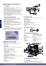
2.2 ELECTRICAL CIRCUIT

The main components of the electrical and electronic circuit are the following:

1. Plug

2. Start switch (RED light)

3. Push button for brush (BLACK)

4. Motor

5. Transformer

6. LED lighting diodes

7. Connection plate

2.3 TECHNICAL DATA

Motor: Single phase 220V; 50Hz; 0,25Kw; 1,500 rpm (Optional: 110V; 60Hz; 0,25Kw; 

1,500 rpm)

Cutter: FP19 HSS (Ø80x1.4x16)

Cutter speed: 750 rpm

Transmission: Ribbed belt.

Clamps: Self-centring

Movements: Guides with roller cages

Useful courses: X = 62 mm; Y = 47 mm

Lights: Led

Dimensions: Width = 370 mm; Depth = 460 mm; Height: 260 mm

Weight: 26 Kg 

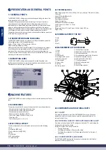
2.4 NOMENCLATURE OF THE KEY

1. Head

2. Stem

3. Bit

4. Teeth

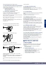
2.5 MAIN ELEMENTS OF THE MACHINE

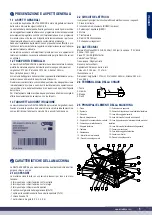
1.- Cutter

2.- Brush

3.- Clamp

4.- Clamp handle

5.- Carriage forward control

6.- Round point control

7.- Probe support

8.- Copier index

9.- Lighting

10.-Start-up switch

1

2

3

4

5

6

7

8

9

10

11

12

13

14

15

16

17

18

19

20

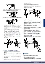
2.6 COMPONENTS AND FUNCTIONAL PARTS
2.6.1 CLAMP

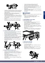
The clamp is a fundamental part of the DELTA ADVANCE machine. It has been 

studied to be able to cut as many keys as possible, using counterpoints for the 

cutting of some of them.

2.6.2 ROTATION LOCK OF THE RIGHT-HAND SIDE CLAMP

The clamp on the right side of the BIT carriage has the handle “16”, which allows the 

locking and unlocking of the rotation.

Locking the rotation of this clamp is useful for:

• 

Copying frontal keys.

• 

Facilitating the fastening of the keys in the clamp.

• 

Facilitating the realization of the “bit stop against the cutter” (in the case of 

short keys).

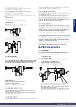
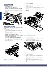
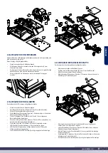
2.6.3 COUNTERPOINTS (USE MODE)

The DELTA ADVANCE machine has three pairs of counterpoints, to facilitate the 

attachment of different types of keys:

11.- Push button of the brush

12.- Adjustment control in depth of the probe

13.- Carriage fixing handle

14.- Carriage locking handle in the X direction

15.- Handle for the probe’s spring

16.- Grip lock handle of the clamp

17.- Tray for accessories

18.- Hole for locking the head

19.- Chip tray

20.- General power socket

1

2

3

4

Summary of Contents for ERREBI DELTA ADVANCE

Page 1: ...MACCHINA DUPLICATRICE DELTAADVANCE MANUALE D ISTRUZIONE KEY CUTTING MACHINE DELTAADVANCE INSTRUCTION MANUAL KOPIERMASCHINE DELTAADVANCE ANWEISUNGSHANDBUCH MACHINE A TAILLER LES CLES DELTAADVANCE NOTICE D UTILISATION ...

Page 2: ......
Page 3: ...www errebispa com 3 DELTA ADVANCE MACCHINA DUPLICATRICE MANUALE D ISTRUZIONE ITALIANO www errebispa com 3 ...

Page 4: ...co dell asse X 2 6 7 Blocco dell asse Y 2 6 8 Carrello TAGLI VERTICALI opzionale 3 OPERATIVITÀ E FUNZIONAMENTO 3 1 REGOLAZIONI 3 1 1 Regolazione laterale 3 1 2 Regolazione della profondità di taglio 3 1 3 Regolazione del massimale laterale 3 2 CIFRATURA 3 2 1 Cifratura delle chiavi tipo GORGES 3 2 2 Cifratura delle chiavi A POMPA 3 2 3 Cifratura dei tagli VERTICALI 4 MANUTENZIONE 4 1 SOSTITUZIONE ...

Page 5: ...ola della macchina nome e indirizzo del fabbricante marchio CE e anno di fabbricazione 2 CARATTERISTICHE DELLA MACCHINA La DELTAADVANCE è una moderna macchina duplicatrice di chiavi del tipo gorges e chiavi a pompa 2 1 ACCESSORI La macchina viene fornita con una serie di accessori per l uso e la manu tenzione 2 fermo punta per chiavi femmina con foro stretto 2 fermo punta per chiavi femmina con fo...

Page 6: ... non esistano limiti alla lunghezza della chiave da duplicare Dispone di ganasce su due altezze in modo che la ganascia sul lato sinistro non impedisca l aggancio di chiavi di qualsiasi lunghezza 2 6 5 MECCANISMO A MOLLA DEL TASTATORE La macchina DELTAADVANCE dispone della leva 15 che aziona il mecca nismo a molla del tastatore Il meccanismo a molla del tastatore ne agevola l inserimento tra i den...

Page 7: ...tatore T e nella fresa C Muovendo la leva 12 far spostare il tastatore in avanti o all indietro fino a fare in modo che con il tastatore T appoggiato sullo spillo di regolazione VT la fresa C sfiori leggermente lo spillo di regolazione VC Serrare nuovamente la vite M 16 12 M 15 T C VT VC 3 1 3 REGOLAZIONE DEL MASSIMALE LATERALE Il carrello BIT viene fornito con i massimali laterali regolati di ser...

Page 8: ...e Per le chiavi con doppia mappa girare entrambe le chiavi di 180º e ripetere le operazioni già descritte Eventuali sbavature verificatesi sulla chiave durante la duplicazione potranno essere eliminate utilizzando la spazzola di cui la macchina è stata appositamente dotata 3 2 2 CIFRATURA DELLE CHIAVI A POMPA Bloccare la rotazione della ganascia destra Utilizzare a tale scopo la leva 16 Collocare ...

Page 9: ...in considerazione che la fresa gira in senso orario Estrarre lo spillo A Dopo la sostituzione della fresa si raccomanda di realizzare la Rego lazione di profondità di taglio La procedura è indicata nel punto 3 1 2 del presente manuale A B C E 4 2 SOSTITUZIONE DEL TASTATORE Per sostituire il tastatore procedere come segue Spegnere e scollegare la macchina Allentare la vite F utilizzando la chiave a...

Page 10: ...engono azionati gli interruttori di avanzamento è necessario verificare lo stato dei fusibili Questa operazione va realizzata come segue Spegnere e scollegare la macchina Servendosi di un cacciavite piccolo estrarre il portafusibili U dalla presa di corrente Verificare i fusibili con un tester dato che a vista potrebbero sembrare in buone condizioni pur avendo invece dei difetti elettrici In caso ...

Page 11: ... Accertarsi che la macchina sia provvista di messa a terra Si raccomanda di collocare la macchina a un altezza alla quale l operatore possa lavorare comodamente 6 SMALTIMENTO DEI RIFIUTI Per rifiuto si intende qualsiasi sostanza od oggetto derivante da attività uma ne o da cicli naturali che venga abbandonata o che sia destinata ad essere abbandonata 6 1 IMBALLO Essendo l imballo in cui viene forn...

Page 12: ...12 DELTAADVANCE instruction manual ENGLISH DELTA ADVANCE KEY CUTTING MACHINE INSTRUCTION MANUAL ENGLISH ...

Page 13: ...ment spring 2 5 5 Vertical adjustment of the tracer 3 KEY CUTTING 3 1 KEY CUTTING PROCESS 3 2 KEY CUTTING 3 2 1 SEA 1 key 3 2 2 OP WH P and OP WY P keys 3 2 3 HU HAA P key 3 2 4 BM 6 P key 3 2 5 ME 4 P ME 6 P ME 7 P and ME 8 P keys 3 2 6 KA 2 KA 3 and KA 4 keys 3 2 7 WIN 1D WIN 2D WIN 3D and WIN 4D keys 3 2 8 JIS 4 P key 3 2 9 FO 6 P key 4 MAINTENANCE 4 1 ADJUSTING THE CLAMP 4 2 REPLACING THE FUSE...

Page 14: ...eys with wide holes 2 Counterpoints for special male keys 2 Rods to make the adjustment Ø5x70 1 Rod for the change of cutter or brush 7x70 1 Fixed key of 18 1 Set of Allen keys 2 2 5 3 4 5 6 2 2 ELECTRICAL CIRCUIT The main components of the electrical and electronic circuit are the following 1 Plug 2 Start switch RED light 3 Push button for brush BLACK 4 Motor 5 Transformer 6 LED lighting diodes 7...

Page 15: ...ocking the X axis also facilitates the operation of fastening releasing the keys from its clamps by preventing the carriage from sliding to the sides 2 6 7 Y AXIS LOCKING The machine also has a slight lock at the end of the course of the Y axis to prevent the carriage from sliding forward during the operation of fastening releasing the keys from its clamps Just bring the carriage of the machine to...

Page 16: ... straight groove of approximately 8 mm of depth N1 R C1 Loosen the screw Q that fixes the internal bushing C2 Release the key on the right hand side clamp and attach it to the left side clamp so that the T probe is inserted into the slot that we have made in the key In this key position support the left side of the lateral stop N2 against the bit of the key In this position of the Lateral Stop N2 ...

Page 17: ...BIT carriage is pulled out by pulling it to the right side The clamp carriage for vertical cuts is introduced from right to left until an internal stop is felt Fasten the virgin key and the key to be encrypted in its corresponding clamps operating the S handles The bit of the key must stop against the lower part of the clamp The key bit must rest against the vertical wall of the clamp Start the ro...

Page 18: ...he belt laterally while turning the head with the key No 13 inserted on the nut of the cutter Check that the belt is fitted correctly K N J I O 4 5 MOTOR REPLACEMENT To replace the motor proceed as follows Turn off and unplug the machine Remove the I belt This procedure is indicated in section 4 4 of this Manual Remove the lower protective plate P To do this release the 8 screws that hold it to th...

Page 19: ...d and understood Always disconnect the power supply before carrying out any cleaning or maintenance work Keep the machine as well as its surroundings clean at all times Work with dry hands Always use protective glasses even if the machine already has protective panels Make sure the machine is earthed We recommend working with the machine at a height at which the user is comfortable 6 WASTE DISPOSA...

Page 20: ...20 DELTAADVANCE anweisungshandbuch DEUTSCH DELTA ADVANCE KOPIERMASCHINE ANWEISUNGSHANDBUCH DEUTSCH ...

Page 21: ...egelung der Y Achse 2 6 8 Schlitten für vertikale Schnitte optional 3 FRÄSEN 3 1 EINSTELLELEMENTE 3 1 1 Seitliche Einstellung 3 1 2 Einstellung der Schnitttiefe 3 1 3 Seitenanschlag einstellen 3 2 FRÄSEN 3 2 1 Fräsen von BART Schlüsseln 3 2 2 Fräsen von KREUZBART Schlüsseln 3 2 3 Fräsen von VERTIKAL Schnitten 4 WARTUNG 4 1 AUSTAUSCH DER FRÄSE 4 2 AUSTAUSCH DES TASTERS 4 3 AUSTAUSCH DER BÜRSTE 4 4 ...

Page 22: ...erne Kopiermaschine für Bartschlüssel und Pumpenschlüssel 2 1 ZUBEHÖR Die Maschine wird mit einer Reihe von Zubehör für die Verwendung und Wartung geliefert 2 Reitstöcke für Schlüssel mit kleinem Dornloch 2 Reitstöcke für Schlüssel mit großem Dornloch 2 Reitstöcke für Spezialschlüssel ohne Dornloch 2 Einstellstangen Ø5x70 1 Stange zum Wechseln des Fräsers oder der Bürste 7x70 1 18er Maulschlüssel ...

Page 23: ...ischen die Schlüsselzähne um die Fräse führen zu können 2 6 6 VERRIEGELUNG DER X ACHSE Die Maschine DELTAADVANCE verfügt über einen Knauf 14 der die Bewegung des Schlittens in X Richtung ver entriegelt Die Verriegelungsfunktion der X Achse ist von Nutzen wenn der Schlitten sich nur nach vorne bewegen soll ohne dass seitliche Bewegungen möglich sind Sie ist auch nützlich wenn Schlüssel mit dem opti...

Page 24: ...diese jedoch folgendermaßen einzustellen Rechte Seite des Seitenanschlags N1 an der internen Buchse C1 abstützen In dieser Position die Schraube R festziehen um den Seitenanschlag N1 zu befestigen Einen langen Schlüssel ohne Dornloch in die rechte Spannbacke einspannen sodass der Bart am Seitenanschlag N1 anliegt X Achse des Schlittens durch Betätigung des Knaufs 14 verriegeln Gerade Nut mit ungef...

Page 25: ...nbacken zu erleichtern wird empfohlen die X Achse und die Y Achse zu verriegeln auf diese Weise bewegt sich der Schlitten nicht Fräse durch Betätigen des entsprechenden Schalters einschalten Schlüssel an Fräse und Taster annähern Es wird empfohlen mit Bedacht vorzugehen ohne die Fräse übermäßig zu belasten Während des Kopierens an der Schlüsselkopie entstehende Grate können mithilfe der Bürste ent...

Page 26: ...bgenutzte Bürste J herausnehmen Neue Bürste J einbauen und mit der Schraube H festziehen Nicht zu fest anziehen damit sich die Schraube H beim nächsten Austausch nicht zu schwer löst Stange A herausziehen A J H 4 4 AUSTAUSCH DES ZAHNRIEMENS Der Zahnriemen der Maschine DELTAADVANCE ist elastisch sodass kein Spannen erforderlich ist Sollte ein Austausch des Riemens erforderlich sein folgendermaßen v...

Page 27: ...auen Dazu die 3 Schrauben lösen mit denen die Vorrichtung am Gestell befestigt ist Die beiden Kabel des LED Streifens 9 von der Klemmleiste trennen LED Streifen 9 aus der Halterung mit der er verklebt ist lösen LED Streifen 9 herausziehen sodass die Kabel aus der Öffnung der Halterung herausgezogen werden Der Einbau des neuen LED Steifens 9 erfolgt in umgekehrter Reihenfolge K N C D 9 4 8 AUSTAUSC...

Page 28: ...en wurden oder aufgegeben werden sollen 6 1 VERPACKUNGEN Da das Verpackungsmaterial der DELTAADVANCE aus Karton besteht kann diese Verpackung recycelt werden Als Restmüll ist es wie fester Hausmüll zu behandeln und darf daher nur in speziellen Karton Container entsorgt werden Die Teile die die Maschine in dem Karton schützen bestehen aus einem Polymermaterial das im Restmüll entsorgt werden kann u...

Page 29: ...www errebispa com 29 FRANÇAIS DELTA ADVANCE MACHINE A TAILLER LES CLES NOTICE D UTILISATION FRANÇAIS ...

Page 30: ...alpeur 2 6 6 Blocage de l axe X 2 6 7 Blocage de l axe Y 2 6 8 Chariot de fixation pour COUPE VERTICALE en option 3 FONCTIONNEMENT 3 1 REGLAGES 3 1 1 Réglage latéral 3 1 2 Réglage de la profondeur de coupe 3 1 3 Réglage de la butée latérale 3 2 TAILLAGE 3 2 1 Taillage de clés A GORGE 3 2 2 Taillage des clés FRONTALES 3 2 3 Taillage des coupes VERTICALES 4 MAINTENANCE 4 1 REMPLACEMENT DE LA FRAISE ...

Page 31: ...e l année de fabrication 2 CARACTERISTIQUES DE LAMACHINE La DELTAADVANCE est une machine moderne duplicatrice de clés à gorge et de clés frontales 2 1 ACCESSOIRES La machine est fournie avec divers accessoires conçus pour l utilisation et la maintenance de la machine 2 contre pointes pour clés femelles à orifice étroit 2 contre pointes pour clés femelles à orifice large 2 contre pointes pour clés ...

Page 32: ...ipée de la manette 15 qui permet d actionner le ressort du palpeur L actionnement du ressort du palpeur permet de faciliter l insertion du palpeur entre les dents de la clé pour ensuite guider la clé vers la fraise 2 6 6 BLOCAGE DE L AXE X La machine DELTAADVANCE est équipée de la manette 14 qui permet de bloquer débloquer le déplacement du chariot sur l axe X La fonctionnalité de blocage de l axe...

Page 33: ...les après chaque remplacement pour ce faire suivez les instructions suivantes Appuyez le côté droit de la butée latérale N1 sur le culot interne C1 Une fois sur cette position fixez la butée latérale N1 en serrant la vis R Fixez une clé de type mâle longue dans l étau côté droit en faisant buter le panneton contre la butée latérale N1 Bloquez l axe X du chariot au moyen de la manette 14 Réalisez u...

Page 34: ... la fraise Si au cours de la duplication des ébarbures apparaissent sur la clé dupliquée veuillez les éliminer au moyen de la brosse 3 2 3 TAILLAGE DES COUPES VERTICALES Remplacez le chariot BIT par le chariot de fixation pour COUPE VERTICALE Pour faciliter le remplacement des chariots il est recommandé de bloquer l axe X et l axe Y de la machine Cela permet de maintenir immobile le chariot princi...

Page 35: ...DVANCE est élastique par conséquent aucun réglage de la tension n est nécessaire S il s avère nécessaire de remplacer la courroie suivez les instructions suivantes Éteignez et débranchez la machine Retirez le chariot de la machine BIT ou à COUPE VERTICALE Retirez le tapis K de la partie supérieure Retirez le capot de protection N du moteur Pour ce faire dévissez les 11 vis qui fixent le capot au b...

Page 36: ...rotecteur de la fraise D Pour ce faire dévissez les 3 vis qui fixent le protecteur au bâti Dévissez les 2 câbles du ruban de LED 9 du bloc de connexion Décollez le ruban de LED 9 du support sur lequel il est collé Retirez le ruban de LED 9 de façon à faire sortir les câbles de l orifice du support Pour installer le nouveau ruban de LED 9 réalisez les étapes susmentionnées dans l ordre inverse K N ...

Page 37: ...n carton celui ci peut donc faire l objet d un recyclage En tant que déchet l emballage est considéré comme étant un déchet solide urbain et par conséquent il doit obligatoirement être mis au rebut dans les conteneurs spécialement conçus pour le carton Les coques de protection de la machine à l intérieur de la caisse sont en polymère et par conséquent sont considérées comme étant des déchets solid...

Page 38: ...191 NT 41 TI 105 NT 40 TI 107 TI 107 DX 140 NT 34 DX 142 DX 122 NT 54 DX 123 DX 123 TI 118 NT 58 DX 140 NT 35 DK 200 TI 114 NT 17 NT 16 TI 114 DX 139 NT 33 TI 107 NT 47 EC 215 EC 215 NT 32 DX 140 DX 140 DX 139 NT 47 TI 107 NT 36 DX 132 NT 14 PR 182 CarroBIT III 2018 V 00 TI 98 TI 100 DX 185 M VOL ...

Page 39: ... EC 193 EC 195 DK 207 EC 255 PR 136 EC 77 NT 37 NT 56 EC 14 TI 118 NT 54 DX 123 EC 193 EC 195 DK 207 EC 255 PR 143 EC 198 DX 118 EC 196 EC 197 PR 143 EC 198 NT 48 DK 197 DK 207 DK 198 EC 206 EC 207 ECO 607 EC 207 NT 55 EC 214 EC 235 DX 185 NT 64 NT 65 NT 67 ...

Page 40: ... 53 DK 128 NT 70 DK 180 DX 95 TIN 44 FP 19 TI 73 TI 72 DX 87 DX 89 DX 140 DX 88 DX 87 NT 25 DK 200 TIN 45 C 3 DX 98 TIN 43 NT 6 EC 191 AVN 202 EC 90 DK 193 NT 19 NT 52 GOR 515 CP 101 DX 118 PR 295 NT 61 DK 207 PR 144 PR 301 NT 71 CP 101 PR 145 NT 29 DX 175 DELTA ADVANCE IV 2018 V 01 PR 295 CP 58 CP 57 PR 295 PR 301 PR 223 PR 301 PR 295 PR 223 PR 295 PR 223 NT 50 CP 58 CP 57 PR 295 PR 223 PR 295 CP...

Page 41: ...le Cibiana BL ITALY Tel 0435 542 500 Fax 0435 542 522 www errebispa com info errebispa com Errebi Deutschland GmbH Velbert Germany Tel 02053 49 62 0 Fax 02053 49 62 22 www errebi gmbh de info errebi gmbh de YOURKEY Member of ...

Reviews: