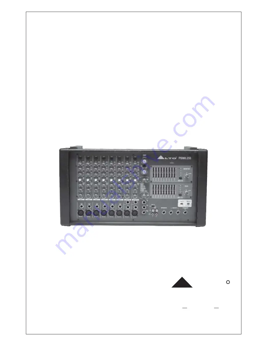
PBM8.250/
PBM8.500
8-channel
Stereo Powered Mixer with DSP
User's Manual
LTO
R
www.altoproaudio.com
Version 1.2 August 2004
English
Page 1: ...PBM8 250 PBM8 500 8 channel Stereo Powered Mixer with DSP User s Manual LTO R www altoproaudio com Version 1 2 August 2004 English...
Page 2: ...to qualified service personnel only Do not perform any servicing other than those instructions contained within the User s Manual When required either blow off dust from the product or use a dry cloth...
Page 3: ...ing future products for you We guarantee you our commitment for quality continual research and development and We would like to thank all the people who made the LTO PBM8 250 500 possible especially...
Page 4: ...nel Section 4 2 MASTER SECTION Control 4 3 MASTER SECTION INPUT and OUTPUT Jacks 4 4 DSP Section 4 5 Rear Panel 5 PRESET LIST 15 6 INSTALLATION AND CONNECTION 22 6 1 Audio Connections 6 2 Speaker Conn...
Page 5: ...r two aux sends pan and level control The master section includes stereo return 2 track input output for playing back stereo devices for recording your mix sweet equ alizers for main and monitor 256 p...
Page 6: ...high headroom offering more dynamic range Each input channel with 20dB PAD PAN and level control 3 band equlizer on input channels 256 position multieffect 2 track recording IN OUT phono Headphone ou...
Page 7: ...switch off your PBM8 250 500 before all external devices 3 6 When the external power amplifier or active speaker connected to the main output L R of your PBM8 250 500 please switch on your PBM8 250 5...
Page 8: ...Hz 2 5KHz 2 5KHz 80Hz 80Hz 80Hz 80Hz 80Hz 80Hz 80Hz 80Hz 80Hz 15dB 15dB 15dB 15dB 15dB 15dB 15dB 15dB 15dB 10dB 10dB 10dB 10dB 10dB 10dB 10dB 10dB 10dB 10dB 10dB 10dB 10dB 10dB 10dB 10dB 10dB 10dB 20...
Page 9: ...2 5KHz 80Hz 80Hz 80Hz 80Hz 80Hz 80Hz 80Hz 80Hz 80Hz 15dB 15dB 15dB 15dB 15dB 15dB 15dB 15dB 15dB 10dB 10dB 10dB 10dB 10dB 10dB 10dB 10dB 10dB 10dB 10dB 10dB 10dB 10dB 10dB 10dB 10dB 10dB 20 dB PAD 20...
Page 10: ...0dB 0dB 0dB 0dB 0dB 0dB 0 dB 0 dB LEVEL 3 4 5 6 7 8 3 20dB PAD Button Pressing this button will attenuate the input signal by 20dB In such way you can produce increased headroom and reduce the risk o...
Page 11: ...ontrol fully counterclockwise the signal will be present only on the left of main mix and vice versa PAN Control 8 This control is used to adjust the overall level of respective channel The adjustable...
Page 12: ...mix signal path when some frequency band s fader lights up it means the level of corresponding frequency band is too high which may lead to distortion Via the button you can prevent from the signal di...
Page 13: ...r or active monitor speaker MONITOR OUT Jack 20 The both jacks are used to output the main mix signal to an external amplifier or active speaker MAIN OUT Jacks 21 This is a stereo phone type output ja...
Page 14: ...rack out left and right Via these jacks you can route the main mix signal into a tape recorder or DAT for recording 2 TRACK OUT 27 Adjust this knob to select the right effect you wish to perform There...
Page 15: ...tention to the impedance of speaker Lower load impedances are not permitted SPEAKERS Jacks 34 35 36 32 This control is used to control the volume of signal sent to main mix bus which can be varied fro...
Page 16: ...e delay Rev Time Room Size Rev Type Hi Damp 1 114 45 79 10 55 0 30 84 55 45 50 40 114 45 0 25 Hall 12 2 Spring 3 Plate 4 5 6 7 8 9 10 11 12 13 14 15 16 Spring Hall Plate 12 12 12 12 12 12 12 12 12 12...
Page 17: ...12 00 0 96 12 00 0 96 12 00 0 96 12 00 0 96 12 00 0 96 12 00 0 96 12 00 2 90 2 90 2 90 3 60 3 60 3 60 4 00 4 00 4 00 4 50 4 50 4 50 88 88 88 88 88 88 88 82 82 82 82 82 82 82 Rev level 04 SMALL HALL N...
Page 18: ...0 100 92 92 92 Rev level 07 PLATE No Pre delay Rev Time Room Size Hi Damp 1 10 10 10 10 10 10 10 10 10 10 10 10 10 10 10 10 2 2 08 3 4 5 6 7 8 9 10 11 12 13 14 15 16 6 10 5 40 4 50 4 00 3 60 2 90 2 40...
Page 19: ...87 2 0 96 12 00 3 4 5 6 7 8 9 10 11 12 13 14 15 16 5 4 5 4 4 50 4 50 4 4 3 60 3 60 2 90 2 90 2 40 2 40 1 70 1 70 1 30 1 30 35 35 33 33 30 30 28 28 22 22 22 22 22 22 22 22 0 96 12 00 0 96 12 00 0 96 12...
Page 20: ...73 74 73 73 12 FLANGER No 1 2 3 4 5 6 7 8 9 10 11 12 Mod Freq 2 79 2 52 2 33 2 25 2 10 1 99 1 75 1 61 1 34 1 22 1 00 0 80 Pitch Depth 30 40 40 40 40 40 40 50 50 70 70 70 Left F B 38 42 38 38 42 38 42...
Page 21: ...B 48 28 28 28 28 28 28 28 48 28 28 28 28 28 28 28 Right F B 82 67 67 67 60 49 49 49 82 67 67 67 60 49 49 49 Rev level 80 80 80 80 80 80 80 80 90 90 90 90 90 90 90 90 Rev Time 15 REVERB FLANGER No 1 2...
Page 22: ...0 1 00 Room Size 39 39 39 39 39 39 39 39 26 26 26 26 26 26 26 26 Mod Freq 4 74 4 12 3 67 3 02 2 63 1 99 1 35 0 50 4 74 4 12 3 67 3 02 2 63 1 99 1 35 0 50 Pitch Depth 40 40 40 40 40 40 70 70 40 40 40 4...
Page 23: ...is point and you are now in the position to successfully operate your PBM8 250 500 However we advise you to read carefully the following section to be the real master of your own mix Not paying attent...
Page 24: ...ignal source equipment for the passive speaker cabinets The power connector has four terminals 1 1 2 2 Your PBM8 250 500 features three modes for connecting the main speakers The speaker impedance req...
Page 25: ...MAIN MONITOR BRIDGE Use either the speakon jacks or phone jacks Main Speaker Main Speaker OUTPUT 2 1 1 POS NEG LEFT MONO MAIN OUTPUT 2 OUTPUT 1 OUTPUT 2 2 2 POS NEG RIGHT MONITOR OUTPUT 1 1 1 POS NEG...
Page 26: ...MONITOR BRIDGE ON 30 30 10 10 0 0 10 10 0 9 9 15 15 0 9 9 15 15 0 9 9 15 15 0 9 9 15 15 HEADPHONE OUT LOW NOISE PREA M P LOW NOISE PREA M P LOW NOISE PREA M P LOW NOISE PREA M P LOW NOISE PREA M P LO...
Page 27: ...el Insert return 2 5kOhm All other inputs 10kOhm or greater Tape out 1kOhm All other output 120Ohm Hi shelving 15dB 12kHz Mid bell 15dB 2 5kHz Low shelving 15dB 80Hz A D and D A converters 24 bit DSP...
Page 28: ...210 240V T3 15AL Physical Weight PBM8 250 Net 14kg 30 86lb Gross 15kg 33 07lb Dimension W D H 550mm 220mm 310mm 8 66 12 20 21 65 Stereo mode 250W 4ohm 190W 8ohm Bridge mode 500W 8ohm PBM8 500 Stereo...
Page 29: ...LTO of 1 year from the purchase date if you have completed the Warranty Registration Card in time 3 3 During the warranty service may repair or replace this product at its own option at no charge to...
Page 30: ...altoproaudio com Tel 886 4 22313737 email alto altoproaudio com Fax 886 4 22346757 All rights reserved to ALTO All features and content might be changed prior notice Any photocopy translation or repr...