background image

Commissioning 

Instruction manual 91/104 V9.2

5.5.1   Resolver card 01/324

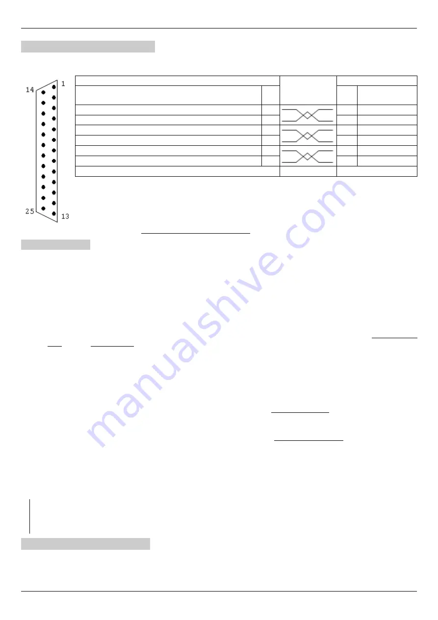
This card makes it possible to connect a resolver to 2 or more poles on the X14 connector and to use it to control the motor.
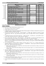
Assigning connector PINs:

DRIVE (Connector X14)

CONNECTION

MOTOR

SIGNAL

N.

PIN

N.

PIN

SIGNAL

Input sine+ (terminal 1 of the secondary winding 1)

19

Input sine-(terminal 2 of the secondary winding 1)

20

Input  (terminal 1 of the secondary winding 2)

21

Input Cosine-  (terminal 2 of the secondary winding 2)

22

Output Resolver supply (terminal 1 of the first winding)

23

Output Resolver 0V (terminal 2 of the first winding)

24

0V (cable shield) – Connector case

View connector from the soldering side (Connector type “D " 25 pole female).

5.5.1.1   Settings

Follow these points for proper commissioning of the transducer card:

1. Check that the X4 connector has no connection.
2. Plug the transducer connector onto X14.
3. Provide service power to the drive and perform all standard settings (paragraph "Calibration and adjustments“ on page 57

and paragraph "Setting motor parameters“ on page 57).

4. Navigate the drive menu to the “Quick setup → Motor Parameters → Feedback Type " parameter. Use the keys to change

setting and select “Resolver ". If you cannot select this transducer, see step 6 just ahead to check if the  card is working prop-
erly.

5. Scroll through the menu to the parameter “Quick setup → Motor Parameters → Resolver Pole Pair ". Set the number of pol


 e  

pairs resolver. ATTENTION: the number of “pole pairs " is half the number of “poles" of the resolver; generally, the number
of poles is indicated on the plate, so the data to be set in this parameter is half the value written on the plate.

6. Check if the card is compatible and if it has been recognised by moving to the menu “Diagnostic → Transduc. Board →

Transduc. Board for...." and verify that the words "Resolver" are present. If this does not occur, please contact the ALTER
Technical Office for some verifications.

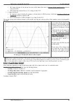
7. Check the amplitude of the signals and the connection of the electrical wires of the transducer by moving to the menu "Dia -

gnostic → Transduc. Board → Resolver Signal" and verify that there is "OK", otherwise make these adjustments:

Written “LOW ": Rotate the trimmer next to the X14 connector in the clockwise


  direction


 , until the inscription changes

and becomes “OK ". If you reach the trimmer limit switch and the writing remains unchanged, you must check the cable
connections to the resolver or the compatibility of the signal with the card.

Written “HIGH”: Rotate the trimmer next to the X14 connector in the anticlockwise direction little at a time, until the
inscription changes and becomes “OK”. If you reach the trimmer limit switch and the writing remains unchanged, you
must check the cable connections to the resolver or the compatibility of the signal with the board.

8. IIf   all   previous   verifications   are   positive,   autotune   of   motor   parameters   can   be   performed   as   explained   in   paragraph

”Autotune for the calculation of optional parameters“ on page 58.

9. At the end of the autotune procedure, the parameters must be stored in order to complete the commissioning of the transducer

card.

NOTE:

 Using a resolver with 4 or more poles you get 2 or more sinusoids per revolution of the motor. For this reason the signal of

the Simulated Encoder or that of the motor position are referred to the single sinusoid. For example, with a 6-pole resolver you get
3 sinusoids per motor revolution; so if the simulated encoder is set to 1024 PPR (pulse/revolution) you will actually get 1024 x 3 =
3072 Impulses per motor lap, and 3 pulses of passage over zero (ZERO tick).

5.5.2   Sin-Cos card 01/325

This card makes it possible to connect a sinusoidal encoder on the X14 connector and to use it to control the motor.
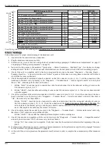
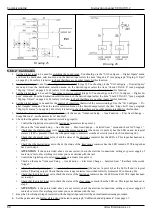
Assigning connector PINs:

60 

Alter Elettronica s.r.l.

Summary of Contents for PWM3D-000

Page 1: ...PWM Digital for asynchronous motors with transducer Instructions Instructions manual manual 91 104 91 104 Version Version 9 2 9 2 Date Date 26 05 2021 26 05 2021 Compatible with Firmware V Compatible...

Page 2: ...ections 13 4 4 Signal connections 14 4 5 Commands starting sequence 20 4 6 Commands shutdown sequence 20 4 7 Restarting after an alarm 20 5 Commissioning 21 5 1 Menu structure 21 5 2 Navigation in the...

Page 3: ...disconnected before any maintenance is carried out Before starting inspection please wait at least 2 minutes after switching off voltage make sure the LEDs and LCD display are switched off Maintenance...

Page 4: ...s in force in the country where the drive is installed Appropriate preparation must be given to operators and machine operators The drive can cause radio frequency interference if it lacks the appropr...

Page 5: ...utput drive 10 Maximum current peak dispensable from the drive 2 2 Declaration of conformity The ALTER Elettronica S r l declares that in the conditions specified in this document the drives CDM model...

Page 6: ...26Arms 036 36Arms 044 44Arms 056 56Arms 070 70Arms 087 87Arms 095 95Arms 111 111Arms 130 130Arms 200 200Arms 440 440Vac 480 480Vac 000 General asynchronous motor control 010 General asynchronous motor...

Page 7: ...L2 L3 A B C Rest R X3 X6 X7 X9 X10 X11 X12 2 3 10 6 12 1 150 RES32R1KW5 23 020 17 001 16 684 2 5 2 5 1 5 16 10 20 1 150 RES32R1KW5 23 020 17 001 25 684 4 2 5 1 5 21 13 26 1 150 RES20R900W10 23 003 17...

Page 8: ...of the drives V I u Pa 1 73 V a The apparent power and current value thus calculated are valid only if the motors always work under the conditions considered in the calculations during normal operatio...

Page 9: ...le drive Speed ramp rating Alarm reset command 4 programmable inputs Opto isolated logic outputs 24Vc 100mA max protected against overload and short circuit Report no alarms Converter ready No 4 progr...

Page 10: ...inductance of at least 100 uH sized for the current absorbed by the drive and having a saturation current equal to at least twice the rated current see Drawing 1 on page 11 From a transformer with con...

Page 11: ...Instruction manual 91 104 V9 2 Installation 4 Installation Drawing 1 Connection to a three phase power line PWM3D 000 only Alter Elettronica s r l 11...

Page 12: ...ect to a good ground the ground terminal placed on the right side of the drive terminal Follow the link patterns in the manual carefully Use shielded cables for signal and power connections Connect to...

Page 13: ...able on the transducer connector 4 3 Power connections To identify the location of the connectors on the drive see Drawing 29 on page 85 and Drawing Drawing 30 on page 86 4 3 1 Three phase or single p...

Page 14: ...he three phase power supply locks L1 L2 L3 must be the same for all drives and must be supplied and removed simultaneously using a single contactor or multiple con trolled contactors at the same time...

Page 15: ...ed encoder if you use a transducer connected to the X14 connector and in this case you can select the simulated encoder type see paragraph Emulated encoder on page 56 The connection cable must be shie...

Page 16: ...8Vcc to 30Vcc nominal 24Vc c States of exits Off Floating On Connected to 24V power supply D24 marked by the lighting of the corresponding led Maximum current for each output 100 mA voltage drop insid...

Page 17: ...elf if the total current absorbed by the loads connected to the outputs does not exceed 100mA connect D24 with clamp 24V X9 and D0V with A0V clamp X12 If the internal power supply cannot be used an ex...

Page 18: ...y shielded cables and connect the ends of the shield to reduce noise Below are some sample drawings for a correct use of the various signals on X11 Drawing 8 Connection of a potentiometer to provide t...

Page 19: ...he speed ramp on the CNC and not that of the drive must be used 3 RTD Reset input It allows you to exit the alarm state and restore the drive s operation after removing the cause that gen erated it Al...

Page 20: ...tputs remain in the ON state and it is possible to give the speed reference resulting in motor rotation 4 6 Commands shutdown sequence Please refer to the connectors Connector X9 on page 16 and Connec...

Page 21: ...layed when using a certain type of transducer or if an optional card is mounted Each menu is made up of 3 different zones 1 At the top indicates the inscription that will be read on the display At the...

Page 22: ...0 MAX SPEED at Pn RPM 0 FEEDBACK TYPE Not sel ENCODER LINES ppr 0 ABS SIGNAL C D YES RESOLVER POLE PAIR 0 AUTOTUNE MODE Disabled Optional param menu at level 3 NOMINAL SPEED RPM 0 FDBK DIRECTION norm...

Page 23: ...PROP 1 P1 20 00 SPEED LP PROP 2 P2 20 00 SPEED LOOP INT 1 I1 0 20 SPEED LOOP INT 2 I2 0 20 SPEED LOOP GAIN SCALE 10 0 An Inp 1 Gain 1 1 0000 An Inp 1 Gain 2 0 0500 An Inp 1 Offset 0 00 An Inp 1 Sign...

Page 24: ...vel 3 An Inp 1 Dest NotUsed An Inp 1 Gain 1 1 0000 An Inp 1 Gain 2 0 0500 An Inp 1 Offset 0 00 An Inp 1 Sign Normal An Inp 1 Value ANALOG INPUT 2 menu at level 3 An Inp 2 Dest NotUsed An Inp 2 Gain 1...

Page 25: ...ed An Inp 4 Gain 1 0000 An Inp 4 Offset 0 00 An Inp 4 Value ANALOG OUTPUTS menu at level 2 ANALOG OUTPUT 1 menu at level 3 An Out 1 Source Mot Load An Out 1 Value An Out 1 Gain 1 0000 An Out 1 Offset...

Page 26: ...3 An Out 3 Source M Torque An Out 3 Value An Out 3 Gain 1 0000 An Out 3 Offset 0 00 An Out 3 Abs True ANALOG OUTPUT 4 menu at level 3 An Out 4 Source OverLoad An Out 4 Value An Out 4 Gain 1 0000 An Ou...

Page 27: ...g Enab Dig Inp 2 Sign Normal Dig Inp 2 Value DIGITAL INPUT 3 menu at level 3 Dig Inp 3 Dest Gain Sel Dig Inp 3 Sign Normal Dig Inp 3 Value DIGITAL INPUT 4 menu at level 3 Dig Inp 4 Dest Pos Enab Dig I...

Page 28: ...p 2 Source SpdThr1 Dig Op 2 Value Dig Op 2 Sign Normal DIGITAL OUTPUT 3 menu at level 3 Dig Op 3 Source Peak Mot Dig Op 3 Value Dig Op 3 Sign Normal DIGITAL OUTPUT 4 menu at level 3 Dig Op 4 Source Po...

Page 29: ...EDBACK RPM MOTOR FREQUENCY Hz MOTOR LOAD MOTOR VOLTAGE MOTOR VOLTAGE V MOTOR TORQUE DC BUS VOLTAGE V HEAT SINK TEMP C CAPACITOR TEMP C DSP TEMP C Transduc Board menu at level 2 Transduc Board for Firm...

Page 30: ...status Internal alarm status Compatible encoder ADVANCED SETUP menu at level 1 ALTER MENU menu at level 2 Enter PassWord SPEED RAMP menu at level 2 RAMP Source AnInp1 SPEED RAMP Time Sec 6 0 DIGITAL R...

Page 31: ...ec 4 0 ELEC GEAR CHANGE menu at level 3 STAGE FUNCTION Disabled SELECTED GEAR Copy from Stage0 CHECK CONTACTORS Enabled EXT TORQUE LIMIT menu at level 3 TORQUE LIMIT Disabled LIMIT SETPOINT 99 99 LIMI...

Page 32: ...P 0 10 Integr Gain I 0 0001 Position Speed RPM 100 Position Window 1 0 Actual Position Position 0 0 00 Position 1 90 0 Position 2 180 0 Position 3 90 0 JOG FUNCTION menu at level 3 JOG ref Mode Fixed...

Page 33: ...delay Min 10 SUMMING BLOCK menu at level 3 Input 1 Input 2 Input 3 Input 4 Output Summ1 Output Summ2 Output Summ3 PID SPEED LOOP menu at level 2 Proport Gain 1 P1 20 00 Proport Gain 2 P2 20 00 Filter...

Page 34: ...roport Gain P 4 00 Integr Gain I 0 01 DRIVE SETUP menu at level 2 Emulated Encoder menu at level 3 Encoder resol PPR 1024 Position offset 0 00 DIRECTION Normal Torque Filter Disabled Power Supply from...

Page 35: ...eed menu 6 To change this parameter you need to switch to Edit Parameter mode Therefore you must press the button once again which causes a to appear in the bottom left corner 7 Press the key to incre...

Page 36: ...is changed Nominal Frequency Minimum Maximum Units of measure 10 499 9 Hz Set the rated motor frequency as indicated on the plate usually between 50 and 60 Hz Normally this value is written on all mo...

Page 37: ...g parameters Nominal Voltage Nominal Frequency Motor Pole Maximum Voltage the above parameter is automatically set to the value calculated by the drive Feedback Type Select the type of transducer moun...

Page 38: ...onal and can be calculated automatically by the Autotune procedure Magnet current Minimum Maximum Units of measure 0 1 Nominal Current 0 9 Amperes RMS Set the motor magnetising current or the unladen...

Page 39: ...nc HighSpd mode and the motor is running at high speed if you notice a speed instability pecking after a change then you have to reduce this value Conversely if you want more accuracy of response and...

Page 40: ...reach the menu Memo Parameters Save 2 In the bottom line is the words UP to confirm Press the button to enter the change parameter mode 3 The character appears in the lower left corner of the display...

Page 41: ...ent to entry 1 of the summing block see section 5 6 14 on page 75 Inp 2 SummBlock The analog input is sent to entry 2 of the summing block see section 5 6 14 on page 75 Inp 3 SummBlock The analog inpu...

Page 42: ...utgoing analog reference Using the keys you can select the source from among these NOT USED the analog output is not used and the Value is always at 0 Motor load the analog output standard on AO1 indi...

Page 43: ...ctivating this function it is possible to have an analog output always positive or negative just set the Gain with a negative number in case of use with unmarked display tools See Drawing 16 to figure...

Page 44: ...inputs are accidentally assigned to the same function the one that has priority over the oth ers is the one with the highest number e g input DI3 has priority over input DI1 Dig Inp X Sign With this...

Page 45: ...can set a reporting tolerance with the parameter indicated in paragraph Position Window on page 50 For more in formation see paragraph Positioner on page 74 Dig Op X Value Read only parameter that ind...

Page 46: ...be connected to the X14 connector Firmware version major Larger version number of the optional transducer card that is installed inside the drive Firmware version minor Minor version number of the opt...

Page 47: ...d ramp that can be inserted with the external command REN see paragraph Connector X12 on page 19 In the following drawing you can see how the ramp block is structured Ramp Source Parameter that allows...

Page 48: ...motor brakes until it stops and then disables the drive Den Function With this menu you can change the operation of the DEN digital input The possible settings are DRIVE DIS ENAB This is the standard...

Page 49: ...ve not been closed The possible selections are as follows DISABLED Digital inputs with the Check STAGE function are not used and are therefore available for other functions The drive cannot know if co...

Page 50: ...control on the communication bus shall not affect the safety of operation in fact other controls are still active that come into operation if the communication between master and slave is interrupted...

Page 51: ...s Set the position to reach and maintain the motor shaft when quota 3 is selected and motor positioning enabled Jog Function Set of parameters to adjust the function of JOG see paragraph JOG function...

Page 52: ...utput see section Dig Op X source on page 44 the overheating of the motor but continues to operate regularly From that moment the CNC or PLC must decide whether to stop the machine or continue the mac...

Page 53: ...o NOT have already saved the parameters with the Memo Parameters menu see page 40 Proport Gain 1 2 Minimum Maximum Units of measure 0 999 00 This parameter modifies the Proportional time constant of t...

Page 54: ...frequency above the rated one parameter Nominal Frequency on page 36 When the inverter is set to Async HighSpd mode and the motor is running at high speed if you notice a speed instability pecking aft...

Page 55: ...all steps and test the motor reaction before further changes When you have found the right parameter that meets your needs you can memorise the variations with the Memo Parameters menu see page 40 and...

Page 56: ...essary to change this parameter when the motor runs at speeds higher than its nominal plate speed and then it is weakened field To enter the right parameter it is essential to use the PC connected to...

Page 57: ...raking resistance 5 4 Calibration and adjustments Operations to be carried out 1 Give 230Vac service power supply on the X10 connector 2 Check that the LCD display lights up and that the letters indic...

Page 58: ...nction from the Quick Setup Motor Parameters Autotune Mode menu on ENABLED 2 When the DOK output switches to ON and the green LED DOK turns on you can give the three phase monophase power supply on th...

Page 59: ...use little at a time until the exact value is obtained in the parameter An INP 1 Value If the previous point is in place change the Quick Setup Motor Parameters Maximum Speed menu parameter to reach t...

Page 60: ...rd for and verify that the words Resolver are present If this does not occur please contact the ALTER Technical Office for some verifications 7 Check the amplitude of the signals and the connection of...

Page 61: ...eters Abs Signal C D and select if the absolute channels of the SinCos encoder are present they are the 4 wires connected to pins 19 20 21 22 of the X14 connector 7 Check if the card is compatible and...

Page 62: ...menu to the parameter Quick setup Motor Parameters Encoder Lines Set the number of sinus oids revolution as reported on the plate or technical data of the transducer 6 Check if the card is compatible...

Page 63: ...ed relative to RA can range from 280 mV to 280 mV at most The same values shall be respected for PB and RB The accuracy of the voltage range for PZ and RZ if any is less im portant than other signals...

Page 64: ...by moving to the Diagnostic Transduc Board SinCos signal A and B and verify that there is OK otherwise perform these verifications 1 Written LOW check that you ve connected the cable from both sides...

Page 65: ...e the logical reversal setting of the output see paragraph Dig Op X Sign on page 45 If the speed reference signal has an unstable offset it may happen that the signaling does not occur In this case yo...

Page 66: ...g the speed threshold you want to have standard 30 RPM by going to the menu Advanced Setup Aux Function Speed Threshold Threshold n 1 and changing the number written for the threshold to be changed se...

Page 67: ...ble the drive in this way the CNC must reduce the speed reference to 0 before removing DEN otherwise the motor is no longer controlled and stops by inertia Instead if you want to use the DEN input to...

Page 68: ...1 Move to the Advanced Setup Aux Function Elec Gear Change Selected Gear menu and check for Stage 1 Check that the digital output set to control the motor contactors the one set in point 4 has the LED...

Page 69: ...the parameters that change when selecting Stage 0 or Stage 1 The parameters that will be written here should not be written in paragraph Menu structure from page 21 The empty fields mean that the para...

Page 70: ...imit 5 6 9 1 Generality This function allows you to adjust the motor torque using a selectable analog input or with a fixed value set on the LCD display It should be pointed out that in any case it is...

Page 71: ...p Aux Functions Jog Function Jog ref Speed paragraph Jog ref Speed on page 51 This parameter can also vary while the motor is spinning to see the result obtained NOTE It should be remembered that usin...

Page 72: ...gs appear on the display and that no red LEDs are on 3 On the MASTER drive you should go to the menu Advanced Setup Aux Functions Anti Backlash Anti Back Mode see section AntiBack Mode on page 49 and...

Page 73: ...at the same time the RUN LEDs of both drives must be switched on 17 With a zero speed reference the motors must stand still If this is not the case change the An Inp 1 Offset parameter see page 39 of...

Page 74: ...the necessary positions are only 2 you can use a di gital input otherwise 2 digital inputs are needed To set the digital inputs to be used you can go to the I O Configure Digital Inputs menu and from...

Page 75: ...s that have been selected These values are added together as shown in the drawing Disable Summ1 it can be controlled by a digital input to disable the sending of the sum 1 result to the summation 3 as...

Page 76: ...ion see the section Connector X12 on page 19 6 1 7 DI4 Digital Input 4 Display the status of the external command DI4 to control a certain programmable function associated with this input For more inf...

Page 77: ...e it and see if the message disappears Otherwise notify the ALTER Technical Service 6 4 3 Anti backlash data error This alarm only appears with the anti backlash function activated see section Anti ba...

Page 78: ...capacitive module outside the drive our module 13 007 6 4 8 Clamp Overload This alarm appears when the resistance of the internal clamp to the drive has exceeded the temperature of 135 C The causes of...

Page 79: ...e motor 3 Bad contacts on terminals oxidised or loose TERMINALS 4 Susceptible interruptions of the motor connection cables 5 Current loop time constants too fast In this case check Check the continuit...

Page 80: ...cooling fans or air conditioners of the electrical panel 6 4 16 Lack of one supply phase This alarm appears when the drive detects the lack of ONE power supply phase on L1 L2 L3 The causes that genera...

Page 81: ...y the ALTER Tech nical Service 6 4 24 Trans board missing If this alarm appears it means that the optional card mounted at the X14 connector was previously working but is now no longer vis ible to the...

Page 82: ...n page 57 Operations to be carried out Enter ALL motor data as indicated in paragraph Setting motor parameters on page 57 6 5 4 Full scale of FBK X14 inputs This message appears when the drive detecte...

Page 83: ...Enter the optional motor parameters or perform the Autotune procedure as indicated in paragraph Autotune for the calculation of optional parameters on page 58 6 5 10 Overrun Control Loop If this messa...

Page 84: ...mmand 76 RTD Reset Alarm reset command 76 DI1 Digital Input 1 Digital input control n 1 76 DI2 Digital Input 2 Digital input control n 2 76 DI3 Digital Input 3 Digital input control n 3 76 DI4 Digital...

Page 85: ...Instruction manual 91 104 V9 2 Mechanical characteristics 8 Mechanical characteristics 8 1 Size 1 Mass 4 6 Kg Alter Elettronica s r l 85 Drawing 29...

Page 86: ...Mechanical characteristics Instruction manual 91 104 V9 2 8 2 Size 2 Mass 12 Kg 86 Alter Elettronica s r l Drawing 30...

Page 87: ...Instruction manual 91 104 V9 2 Mechanical characteristics 8 3 Size 3 Mass 14 Kg Alter Elettronica s r l 87 Drawing 31...

Page 88: ...Alter Elettronica s r l Alter Elettronica s r l Via Ezio Tarantelli 7 15033 Casale Monferrato AL ITALY Tel 39 0142 77337 Web http www alterelettronica it email...

Reviews: