Installation & Systems Manual RUBIDIUM SERIES
Page 60
3.25
VD
: Distribution Amplifier
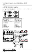
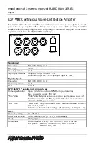
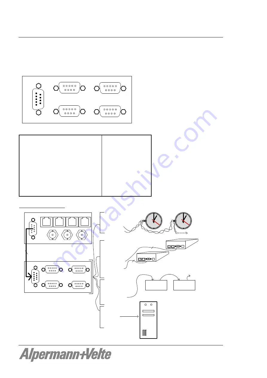
The module is a distribution and amplifier for signals which - for example - are output signals
of the
MTD
connector of the
GT
module.
AlVelte
OUT_2
OUT_1
INPUT
1
1
OUT_4
OUT_3
1
1
1
Pin assignment at connectors OUT_1, OUT_2, OUT_3 and OUT_4:
OUT_1 / OUT_2
1: RS485_TRA_OUT
2: RS485_TRB_OUT or RS232 TxD
3: LTC_OUT_A
4: LTC_OUT_B
5: GND
6: RS422 T-
7: RS422 T+
8: TELEGRAM OUT
9: VCC12_OUT
OUT_3 / OUT_4
1: RS485_TRA_OUT
2: RS485_TRB_OUT
3: LTC_OUT_A
4: LTC_OUT_B
5: GND
6: RS422 T-
7: RS422 T+
8: TELEGRAM OUT
9: VCC12_OUT
Connection Example:
1
VIDEO OUT
VIDEO IN
LOOP OUT
RUB GT: Generator Timecode
GPI B
GPI A
REF IN
MTD
MTD
OUT_2
OUT_1
INPUT
1
1
OUT_4
OUT_3
1
1
1
RUB VD: Distribution
remote
PC or
Server
Connecting
2-Wire Slave Clocks:
OUT_1/OUT_2/OUT_3/OUT_4:
5 = GND
8 = TELEGRAM OUT
Connecting
MTD Operational Units:
OUT_1/OUT_2/OUT_3/OUT_4:
1 = RS485_TRA_OUT
2 = RS485_TRB_OUT
3 = LTC_OUT_A
4 = LTC_OUT_B
5 = GND
9 = VCC12_OUT
Connecting
MTD Displays:
OUT_1/OUT_2/OUT_3/OUT_4:
3 = LTC_OUT_A
4 = LTC_OUT_B
5 = GND
Using RS422:
OUT_1/OUT_2/OUT_3/OUT_4:
5 = GND
6 = RS422 T-
7 = RS422 T+
Pins 1 - 5, long cable,
without DC
Pins 1 - 5 + 9, data + DC
cable length < 20 m
12 1
2
3
4
5
6
7
8
9
10
11
12 1
2
3
4
5
6
7
8
9
10
11
12:59:59
LTC IN - LTC Loop
12:59:59
LTC IN - LTC Loop
Loop
UD Series Displays
USB
1
8 . . . . . 1
8 . . . . . 1
DATA/DC 1
DATA/DC 2
GPI
TCU
USB
1
8 . . . . . 1
8 . . . . . 1
DATA/DC 1
DATA/DC 2
GPI
TCU
1:1
Loop

