


ALNOR
®
ventilation systems
is a legally protected trademark and technical patent. All rights reserved.
56
w
w
w
.al
nor
.c
om.
pl
User Manual
HRU-MinistAIR
6
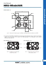
.12 Connecting the ground heat exchanger
Heat recovery unit has a possibility to connect the ground heat exchanger. This function allows you to control
a valve that optionally supply air through the ground-to-air heating system. To do this, install a dedicated
damper with the actuator (DATVTML). Damper works by electric actuator DM-ML-06-230. For quick mounting
of the actuators we recommend specially designed stands DA-SUP-S and DA-SUP-M.
Actuators matching DA-SUP-S mountig plate
Actuators matching DA-SUP-M mountig plate
Alnor DM-ML-06
Alnor DM-ML-06
Belimo CM
Alnor DM-ML-08
Belimo LM
Belimo CM
Belimo TR
Belimo NM
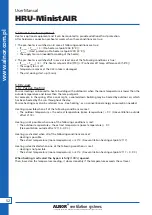
When you mount the actuator to the damper, you should
remember to:
• the damper was open in the HRU-OUTDOOR direction
(not GHE).
• The HRQ-SENS-500 external air temperature sensor should
be routed and connected to the outdoor duct, placed
before the air damper with the actuator. The temperature
sensor should be connected to the X22 connector on the
HRV control board
.
• if the actuator can be mounted in the left-right position, make sure it is mounted correctly as described
below.
In order for the valve to operate correctly, the dumper with
a DM-ML-06-230 electric actuator should be connected
to X28 in the following order:
X28
1
L out 2 (RL1)
2
L (out 1(RL2)
3
N
1
2
3
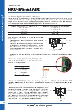
DA4MU24-D/DS
DA4MU230-D/DS
DA6MU24-D/DS
DA6MU230-D/DS
General Damper Actuator
4Nm 6Nm
2-Point and 3-Point
For operation of air control dampers in HVAC system
Toque:4Nm 6Nm
Nominal voltage: AC/DC24V AC100…240V
Control: On/Off /2-Point/3-Point
-DS type include 2 groups of auxiliary switches
Technical Specification
DA4MU24-D/DS
DM-ML-06-24-S
DA4MU230-D/DS
DM-ML-06-230-S
Electrical
data
Nominal voltage
AC24V 50/60Hz DC24V
AC100…240V 50/60Hz
Nominal Voltage range
AC/DC 19.2...28.8V
AC85...265V
Power consumption
3W@Nominal toque
0.5W@Holding
3W@Nominal torque
0.7W@Holding
Wire sizing
0.5mm
2
Functional
data
Torque
4Nm
6Nm
4Nm
6Nm
Damper size
0.8m
2
1.2m
2
0.8m
2
1.2m
2
Direction of rotation
Selectable by switch
Manual override
Gearing latch disengaged by push button, self-resetting
Angle of rotation
Max.95
°
Running time
50S
(
95°
)
70S
(
95°
)
50S
(
95°
)
70S
(
95°
)
Sound power level
45dB
Position indication
Mechanical
Working
conditions
Protection class
Ⅲ
(safety low voltage)
Ⅱ
(totally insulated)
Protection degree
IP44
Ambient temperature
-20…+50
℃
Inventory temperature
-30…+80
℃
Humidity test
95%RH, non condensing
/
EN 60730-1
Dimensions
Weight
Dimensions
See “Dimensions”
Shaft length
>50mm
Shaft diameter
○
6...16mm
□
8X8...12 X12mm
Weight
<0.7Kg
Wiring Diagram
Actuator
DM-ML-06-24(230)
2-Point 3-Point
Auxiliary switch
DM-ML-06-24(230)-S
21
22
23
24
25
26
a
b
Resistance load 3A
,
230V
Inductive load 1.5A
,
230V
actuator
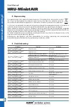
The output to control the geothermal heat exchanger valve, can be configured using
Geothermal Heat
Exchanger Valve Output (#195)
from 0 to1 and disable Frost protection by changing
Frost sensor (#140)
value to 0.
The automatics controls the valve based on the temperature at the
outdoor (Temperature 4 outdoor). If the Temperature 4 outdoor is
lower than the
Geothermal Heat Exchanger Outdoor Temperature
Below (#193
)
or higher than the
Geothermal Heat Exchanger
Outdoor Temperature Above (#194)
the valve will be opened and
the air going to the unit will be taken from the ground heat exchanger.
If the temperature sensor (Temperature 4 outdoor) is broken or if the
above condition is not met the valve will remain closed.
GHE
OUTDOOR
HEAT RECOVERY
UNIT
HRQ-SENS-500
sensor
GHE
OUTDOOR
HEAT RECOVERY
UNIT


